TP-6953 7/19 283Section 16 Additional 4PX/4QX Alternator Information
GC70113B-B/GC70064-E
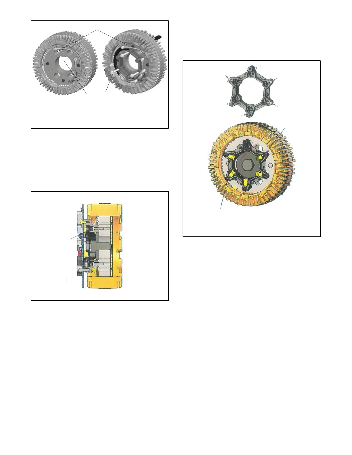
1. Route rotor assembly leads through the hole to the left of
the keyway
2. Rotor assembly leads
3. Exciter armature core keyway
1
2
3
Figure 16 -8 Exciter Armature/Rotor Leads
7. Mount the spacer to the exciter armature using six
thread-forming Torx head screws. See Figure 16-9
and Figure 16-13.
Note: Orient the non-electrical connection mounting
hole to the m ounting hole above the keyway.
1
1. Thread-forming Torx head screws
Side View
Figure 16 -9 Spacer Installation
8. Route the exciter armature and rotor leads (AC1,
AC2, AC3, F1, and F2) around the outer diameter
of the spacer to the inside to eliminate slack. See
Figure 16-10.
Note: Lead connections are identified on the spacer
andinFigure16-10.
Note: Secure excess lead length before attaching
terminals.
9. Use 5 terminals and 5 stainless steel hex nuts to
connect leads AC1, AC2, AC3, F1 and F2 to the
spacer studs. Torque to 1.3 Nm (12 in. lbs.). L ocate
the terminal barrels down inside the spacer pockets.
See Figure 16-10 and Figure 16-13.
No electrical connection
AC1
AC2
AC3
F1
(F+)
F2
(F- )
1
2
1. Route leads around spacer OD to inside to eliminate slack
(leads not shown).
2. Terminals and stainless steel hex nuts.
Terminal barrels located down into spacer pockets.
Figure 16 -10 Spacer Connections
10. If the armature was changed, secure the new
exciter armature by reusing the existing bolt and
bow washer. See Figure 16-11. Torque to 194 Nm
(143 ft. lbs.).
 Loading...

