TP-6953 7/19 99Section 5 Fuel System
Section 5 Fuel System
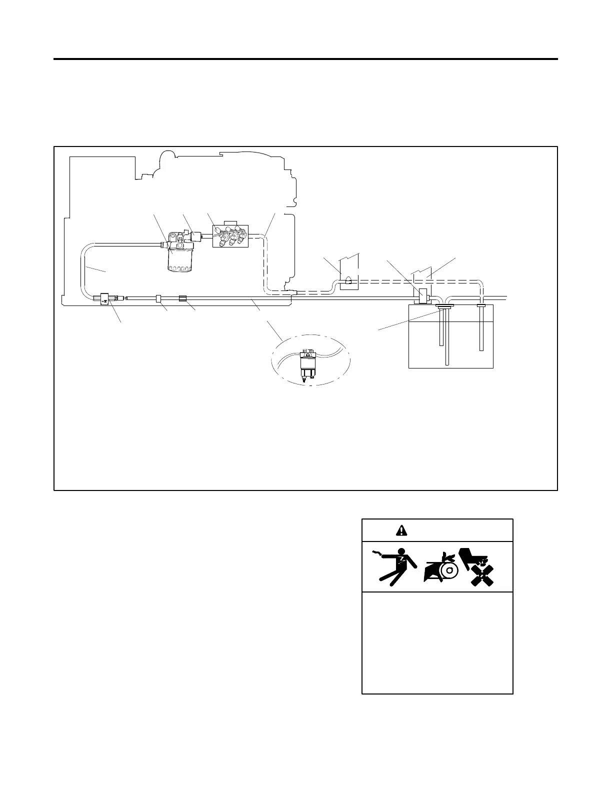
5.1 General
In most installations, both the generator set a nd the
propulsion engine operate from a common fuel t ank with
a dual dip tube arrangement. The generator set’s dip
tube is shorter than the propulsion engine’s dip tube.
With this arrangement, fuel may not be available to the
generator set when the fuel supply is low. See
Figure 5-1 for a fuel system schematic.
7 6
1
542
13
12 11
8
9
1. Fuel lift pump
2. Secondary filter
3. Fuel solenoid
4. Injection pump (non-service side)
5. Fuel return line
6. Permanent supports for fuel system
components
7. Electric fuel or mechanical check valve
(customer provided)
8. Dip tube (customer provided)
9. Fuel tank
10. 14- 24EKOZD/12- 20.5EFKOZD Models:
Primary filter, if equipped (customer
provided).
32- 40EKOZD/28- 35EFKOZD Models:
Shipped loose with unit for customer to
install.
11. Support clamp
12. Clamp
13. Fuel supply line
6
10
To
Propulsion
Engine
3
Figure 5 -1 Fuel System, Typical
5.1.1 Fuel Filt er
The quality and condition of the fuel largely determine
the f ilter’s useful life. Replace the fuel filter element as
listed in the service schedule. Section 1 shows the
typical location of a fuel filter. Use the applicable
procedure below to replace the fuel filter.
Accidental starting.
Can cause severe injury or death.
Disconnect the battery cables before
working on the generator set.
Remove the negative (- ) lead first
when disconnecting the battery.
Reconnect the negative (- ) lead last
when reconnecting the battery.
WARNING
 Loading...

