34 Section 1 Specifications TP-6953 7/19
1.15 Introduction
This service manual provides controller and accessory
troubleshooting and repair information for the following
controller:
D Decision-Makerr 3500
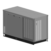
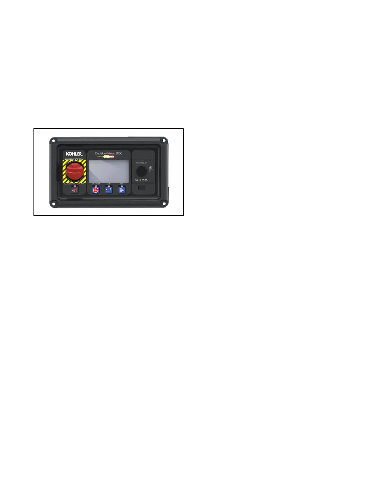
The following illustration identifies the controller.
1.16 Controller Identification and
Features
1.16.1 Decision-Makerr 3500
D AC Output Voltage Regulator Adjustment. The
voltage adjustment provides a maximum
adjustment of ±10% of the system voltage.
D Adjustable Engine Run Speed. Set engine speed
slightly higher or lower than nominal (+49 to - 50
RPM) for passive synchronization.
D Alarm Silence. The controller can be set up to
silence the alarm horn only when in the AUTO
mode for NFPA-110 application or Always f or user
convenience.
D Alternator Protection. The controller provides
generator set overload and short circuit protection
matched to each alternator for the particular
voltage/phase configuration.
D Automatic Restart. The controller automatic
restart feature initiates the start routine and recrank
after a failed start attempt.
D Cyclic Cranking. The controller has programmable
cyclic cranking.
D ECM Diagnostics. The controller displays engine
ECM fault code descriptions to help in engine
troubleshooting.
D Engine Start Aid. Theconfigurablestartingaid
feature provides customized control for an optional
engine starting aid.
D Event Logging. The controller keeps a record (up
to 1000 entries) for warning and shutdown faults.
This fault information becomes a stored record of
system events and can be reset.
D Generator Management. Programmable
generator management based on manual selection,
fuel level, or run time to optimize fuel usage, noise,
maintenance, etc.
D Historical Data Logging. To t al num ber o f
successful starts of the generator is recorded and
displayed.
D Integrated Hybrid Voltage Regulator. The v oltage
regulator provides ±0.5% no-load to full-load RMS
voltage regulation with three-phase sensing.
D Lamp Test. Press the alarm silence/lamp test
button to verify functionality of the indicator lights.
D LCD Display. Backlit LCD display with integral
heater and adjustable contrast for viewing in
varying temperatures and lighting conditions.
D Load Management. Dynamic load add/shed,
based on the present load and available capacity
based on the number of generator sets on the bus.
D Measurement Units. The controller provides
selection of English or metric displays.
D Power Metering. Controller graphical display
provides voltage, current, power factor, kW, kVA,
and kVAR.
D Programming Access (USB). Provides software
upgrades and diagnostics with PC software tools.
D Remote Reset. The remote reset function supports
acknowledging and resetting faults and allows
restarting of the generator set without going to the
master control switch off/reset position.
D Run Time Hourmeter. The g enerator set run time
is displayed.
D Time Delay Engine Cooldown (TDEC). The TDEC
provides a time delay before the generator set
shuts down.
D Time Delay Engine Start (TDES). The TDES
provides a time delay before the generator set
starts.
D Voltage Selection Menu. This menu provides the
capability of quickly switching generator output
voltage. Requires initial activation using SiteTecht
software. NOTE: Generator set output leads may
require reconnection.
D Paralleling Functions:
D Bus sensing
D First on logic
D Synchronizing
D Communication based isochronous load sharing
D Droop load sharing
D External controlled load sharing via analog bias
signals
 Loading...