TP-5936 7/04 29Section 7 Generator Troubleshooting
The following components will be needed to test the
voltage regulator:
D Step-up transformer, 1:2, 120 volts to 240 volts
(1.0 amp min.)
D Variable transformer, 0--140 volts (1.0 amp min.)
D Lamp, 250-volt, 100-watt
D AC voltmeter, 250 volt minimum
D Fuse, 1-amp
D Switch, 1 single-pole single-throw (SPST) 1 amp
(minimum)
D Plug, 120-volt AC (200--240 volt AC plug optional)
D Copper wire, #14 AWG (minimum)
Hazardous voltage.
Can cause severe injury or death.
Operate the generator set only when
all guards and electrical enclosures
areinplace.
Moving rotor.
WARNING
High voltage test. Hazardous voltage can cause severe
injury or death. Follow the instructions of the test equipment
manufacturer when performing high-voltage tests on the rotor
or stator. An improper test procedure can damage equipment
or lead to generator set failure.
Voltage Regulator Test Procedure
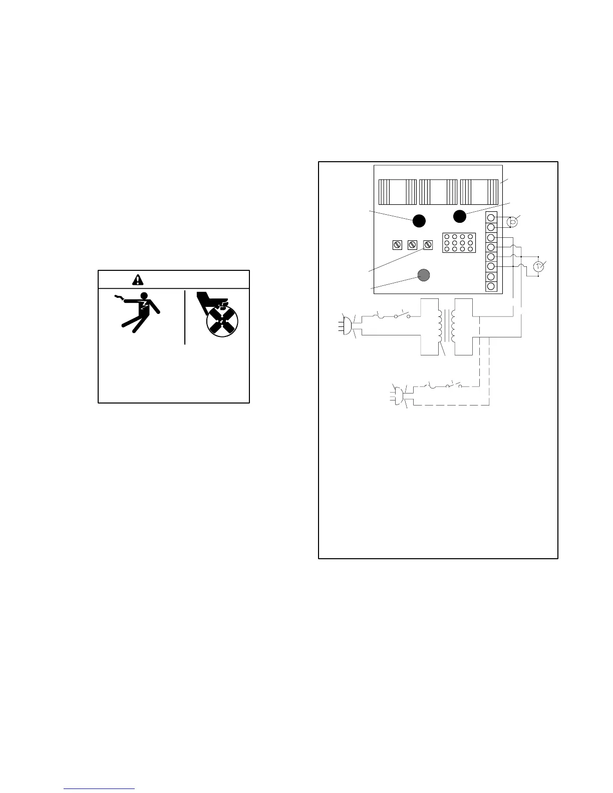
1. Connect the components as shown in Figure 7-3.
If a 200--240 volt power source is available, the
step-up transformer is not required.
2. Turn the volts potentiometer (pot) fully
counterclockwise.
3. Plug the power cord into the outlet.
4. Turn the power supply on. The AC voltmeter
should indicate a power supply voltage of
200--240 volts. The lamp should be off. If lamp is
lit, replace the voltage regulator.
5. Slowly turn the volts adjustment pot clockwise. The
lamp should light. Replace the voltage regulator if
the lamp does not light.
66
55
8
7
6
5
4
3
2
1
Input
Green
Output
Red
STAB
Sensing
Yellow
V/HZ VOLTS
1
2
3
4
5
6
7
8
9
10
11
12
13
14
7
8
11
13
TP-593655
1. LED1 (input)
2. PowerBoostt V voltage regulator
3. LED2 (output)
4. 250-volt, 100-watt lamp
5. AC voltmeter 250 volt (minimum)
6. 1:2 step-up transformer
7. Single-pole single-throw switch
8. 1-amp fuse
9. LED3 (sensing)
10. Volts potentiometer
11. Black wire
12. 100--120 VAC
13. White wire
14. 200--240 VAC (optional)
Figure 7-3 PowerBoostt V Voltage Regulator Test
 Loading...


