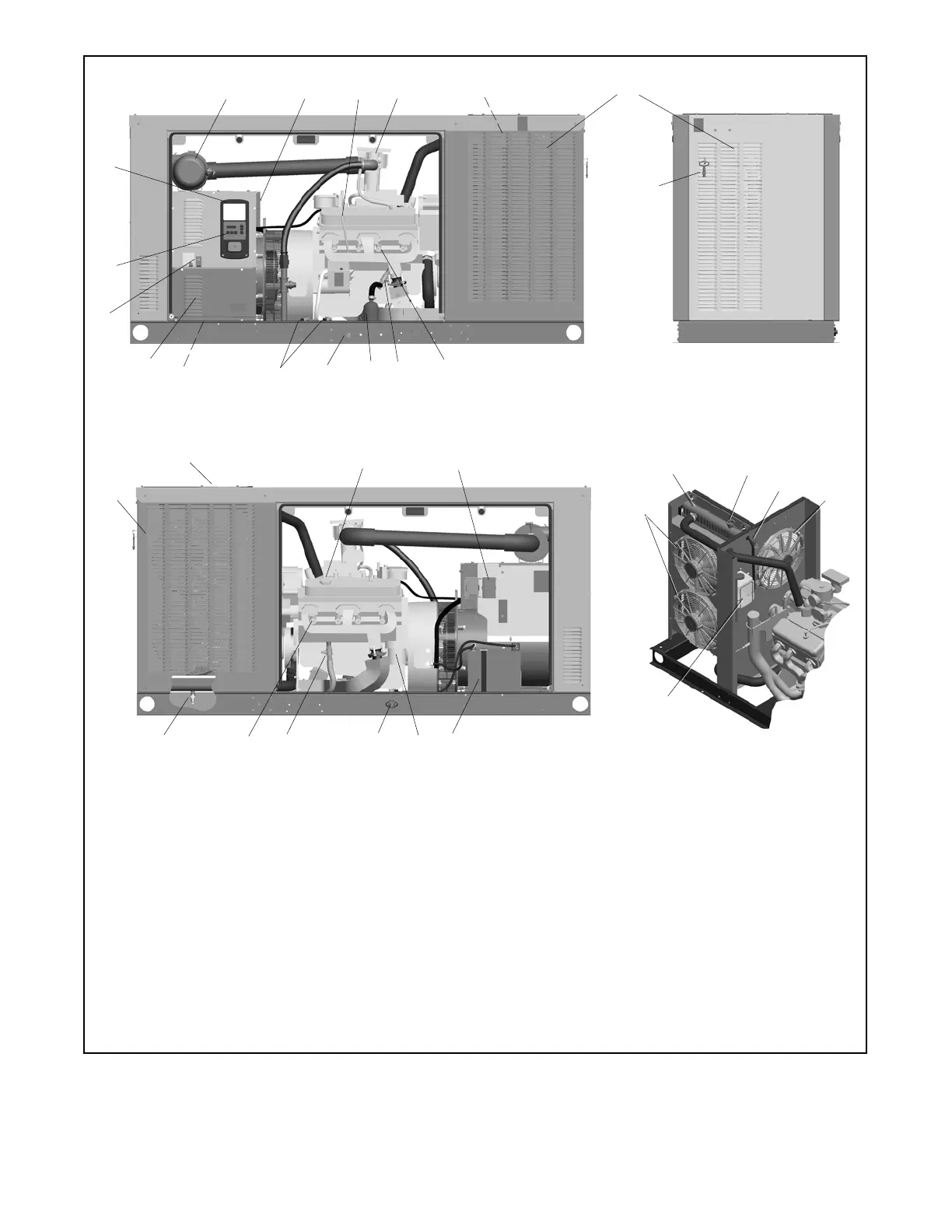
TP-6810 7/1614 Section 1 Service Views
1. Air cleaner
2. Nameplate location
3. Oil check (dipstick)
4. Engine ECM and EPR (electronic fuel pressure regulator)
5. See cooling system detail
6. Exhaust outlet
7. Enclosure locking tool (shipping location only)
8. Spark plugs
9. Block heater connection valve
10. Block heater (optional)
11. Fuel inlet (1 in. NPT)
12. Fuel solenoid valves (two required for UL 2200)
13. Customer load lead access
14. Customer connection access panel
15. Load circuit breaker
16. Generator set master control buttons (on RDC2 controller)
17. RDC2 controller
18. Cooling air inlet (remove this panel to access coolant drain)
19. Access to coolant fill
20. Oil fill (on valve cover)
21. Fan fuses
22. Battery
23. Lube oil filter
24. Oil drain valve
25. Block heater connection valve
26. Coolant drain
27. Fans (qty. 3)
28. Radiator
29. Pressure cap (engine coolant fill)
30. Coolant overflow tube
31. Coolant overflow bottle
ADV-8545
24
15
17
16
28
12
11
1
8
18
2
23
13
14
543
20
22
GM85088
Cooling System Detail
27
27
30
29
26
31
8
6
21
9
25
10
19
7
SERVICE SIDE
NON-SERVICE SIDE
Figure 1-2 Service Views, 48RCLA and 60RCL

 Loading...