TP-7102 9/21 29Section 3 RDC2 Controller Operation
Section 3 RDC2 Controller Operat ion
3.1 RDC2 Generator Set/Transfer
Switch Controller
The generator sets are equipped with the RDC2
generator set/transfer switch controller. The RDC2
controls the following power system components:
D Generator set
D Model RXT automatic transfer switch (ATS)
D Load management device
D Programmable interface module (PIM)
RDC2 Controller features include:
D Two-line x 16 character backlit LCD display with
adjustable contrast
D OFF, AUTO, and RUN generator set master control
buttons
D Generator set status indicating LEDs (OFF, AUTO,
RUN)
D Up, Down, and Select buttons for navigation through
menus and adjustments
D Power system indicator LEDs to show utility and
generator source status, and to show which source
(utility or generator) is supplying power to the building
(Model RXT automatic transfer switch is required)
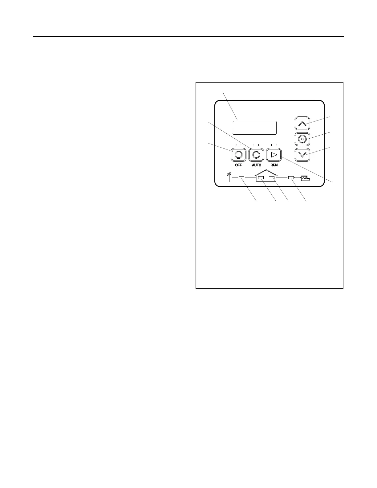
3.2 Controls and Indicators
Figure 3-1 illustrates the keypad, display, and indicators
on the controller’s user interface.
1. 2-line LCD display
2. Up button
3. Select button
4. Down button
5. RUN button and LED
6. Generator power available LED *
7. Generator supplying power to the building LED *
8. Utility supplying power to the building LED *
9. Utility power available LED *
10. OFF button and LED
11. AUTO button and LED
* These LEDs operate only if a Model RXT transfer switch is
connected.
1
10
3
2
5
11
4
GM77569
6789
Figure 3-1 RDC2 User Interface
 Loading...