4
SB-555 5/96
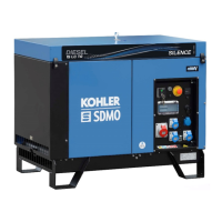
Actuator
(See Figure 5 and Figure 6)
The actuator consists of a stepper motor coupled to the
carburetor throttle shaft.
It receives signals from the governor control unit and
rotates the shaft to the proper position.
To test for proper operation of the actuator, disconnect
magnetic pickup leads. Manually move the throttle
shaft/governor stepper motor fully counterclockwise
(closed throttle). Start generator set. Actuator should
initially moveclockwise(wide-openthrottle)and thenturn
completely counterclockwise. The actuator should
remaininthisposition. Stopgeneratorset. Ifactuatorfails
this test, replace actuator.
The governor actuator should function with steady and
smooth movement during operation. If movement of
actuator is erratic or large changes in movement occur:
D Check shaft alignment—ensure that the actuator
and throttle shafts are concentric and that the
throttle-shaft pinis atmidpoint ofthe actuatorslot
D Check for excessive coupling slot wear—replace
worn parts
D Check for broken or loose wiring including plug
connections
Adjust coupling so throttle shaft pin is recessed to the
middle of the slot.
Stepper-motor rotational position adjustment is not
necessary. Throttle plate position can be either open or
closed during assembly.
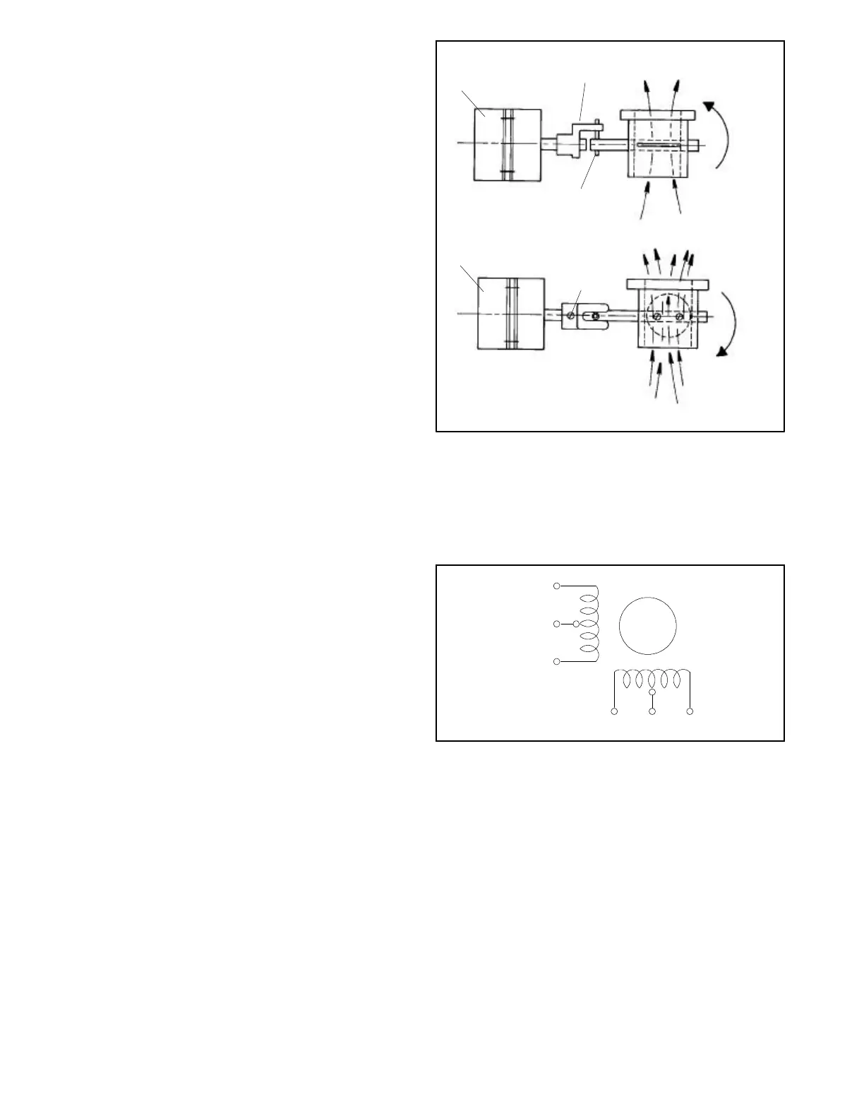
Only two actuator leads of each coil group are utilized.
(BLK-YEL, and RED-WHT.) Resistance per phase: 38.5
ohms.
Voltage pulses received from the governor control
determine movement of the stepper motor.
NOTE
A12-VDCvoltageappliedtothemotorleadswillresultina
single-step movement of 1.8_. Reversal of the voltage
polarity will result in a 1.8_ movement in the reverse
direction.
NOTE
Thesteppermotorwillnotcontinuouslyrotate withbattery
voltage supplied to its windings.
TOP VIEW
1
2
3
4
5
6
7
4
1
TP-5572-6
1. Actuator
2. Coupling
3. Closed throttle
4. Intake air flow
5. Pin
6. Set screw
7. Open throttle
Figure 5. Actuator (Stepper Motor)
YEL
BLK
GRN
RED WHT BLU
TP-5572-6
Figure 6. Actuator Coil Group
 Loading...