5
SB-555 5/96
Governor Control
The electronic control board provides power to the
actuator. It alsocontrols energizing and de-energizingof
the fuel—anti-diesel (AD) solenoid or gas valve.
Prior to any governor adjustments:
1. Open the line circuit breaker between the generator
and any loads which may be frequency sensitive.
2. Connect a frequency meter to the generator AC
output in order to monitor AC output while making
adjustments.
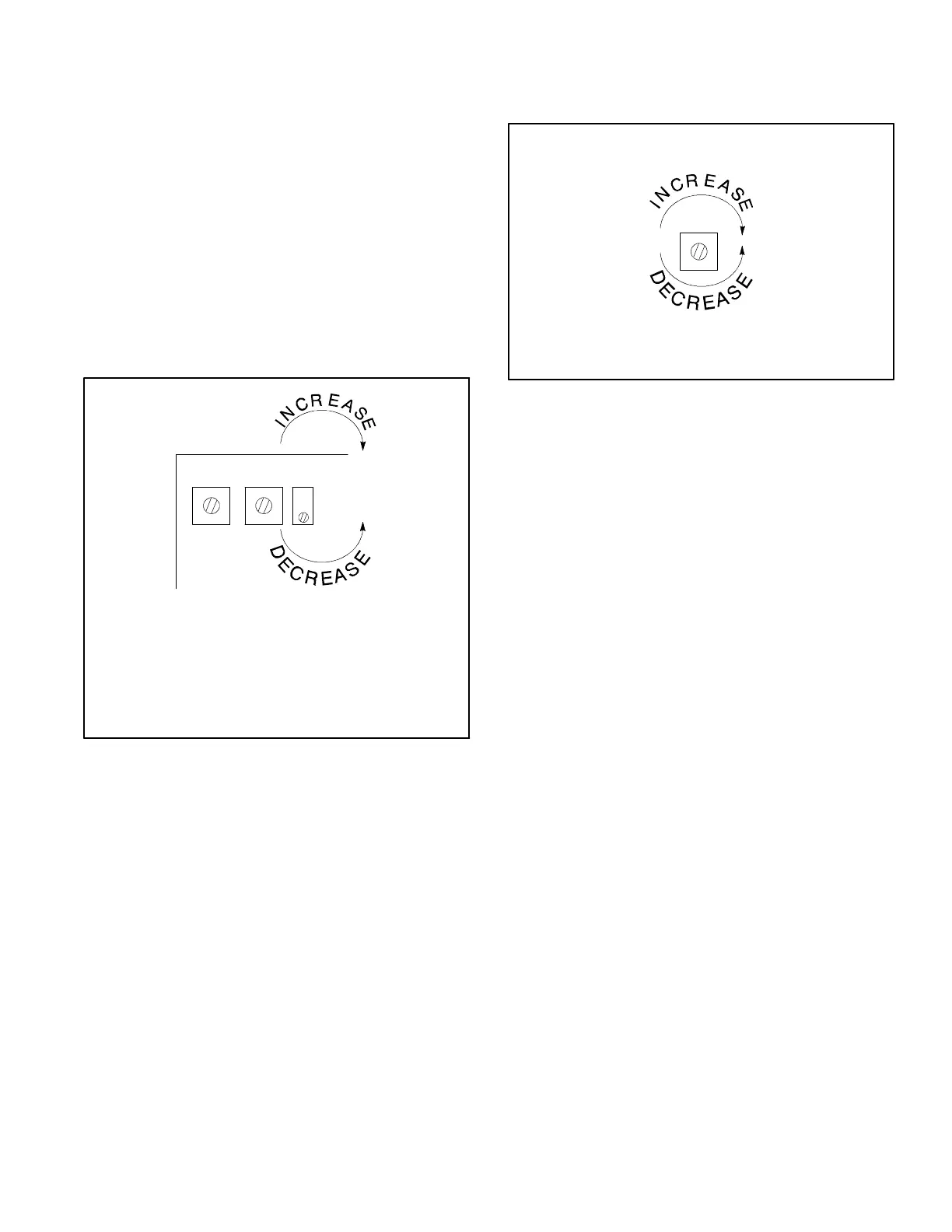
Speed Adjustment
Turn speed potentiometer clockwise to increase speed,
counterclockwise to decrease speed. See Figure 7.
SPEEDGAIN
OVER
SPEED
60 Hz = 1800 RPM
50 Hz = 1500 RPM
4-Pole Generators
TP-5572-6
Figure 7. Speed Potentiometer
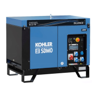
Gain Adjustment
The Gain Potentiometer (Pot) pertains to governor
sensitivity. See Figure 8.
GAIN
TP-5572-6
Figure 8. Gain Potentiometer
D MoveGainPot in1/8-turnincrementsifhuntingor
surging occurs.
D Changing the Gain Pot setting may affect the
governor Speed Pot.
D Governor Speed Pot adjustment will not affect
the Gain Pot.
 Loading...