Do you have a question about the Kohler 7.5EOR and is the answer not in the manual?
Record product identification numbers from the generator set nameplate for future reference.
Record product identification information from the engine nameplate for future reference.
Procedures to prevent accidental starting and associated severe injury or death.
Safety warnings and procedures related to battery handling, acid, and explosive gases.
Precautions against battery short circuits, handling, and electrical discharge.
Safety warnings for fire prevention related to fuel, backfire, and combustible materials.
Hazards associated with exhaust systems, including carbon monoxide poisoning.
Safety precautions for handling fuel systems, including explosive vapors and spills.
Comprehensive safety measures for electrical hazards, shock, grounding, and backfeed.
Precautions for testing live electrical circuits, including personnel and equipment.
Safety measures for dealing with hot components, coolant, steam, and exhaust systems.
Safety precautions for moving and rotating parts, hardware tightening, and servicing.
Notices regarding hardware use, compatibility, and Canadian installation requirements.
Notices for voltage reconnections and marine application restrictions.
Contact information and resources for professional advice and service support.
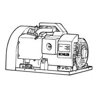
Diagrams identifying key components of the 7.5-10 kW generator set.
Diagrams identifying key components of the 15-20 kW generator set.
Detailed specifications for the engine components across various generator models.
Technical specifications for generator components like rotor, exciter, and stator.
General guidelines and safety precautions for performing maintenance on the generator set.
Information on selecting appropriate engine oil based on operating temperature.
Details on the generator's battery charging alternator and its maintenance.
Procedure for adjusting the alternator/fan belt tension for optimal performance.
Specifications for the 12-volt battery and critical safety precautions for handling.
Comprehensive procedure for preparing the generator set for storage.
Procedure for servicing and replacing the air cleaner element.
Guidelines for inspecting the exhaust system for leaks, damage, and carbon monoxide safety.
Recommended diesel fuel quality and precautions for fuel storage to prevent contamination.
Procedures for replacing the spin-on fuel filter or fuel filter element.
Procedure to bleed air from the fuel system to prevent starting issues.
Information on the governor's function, speed settings, and adjustment procedure.
Description of the water-cooled engine's closed-loop system and radiator-cooled models.
Procedure for checking and maintaining the engine coolant level.
Inspection guide for cooling system components like inlets, radiator, hoses, and belts.
Procedure for safely draining the cooling system for maintenance or storage.
Procedure for flushing and cleaning the cooling system, including mineral deposit removal.
Step-by-step guide for refilling the cooling system with the correct coolant mixture.
Detailed explanation of the controller's operation during start, run, and preheating sequences.
Procedure for stopping the generator set and the controller's sequence during shutdown.
Explanation of engine safety switches and automatic shutdown procedures.
Testing procedures for controller circuit board components, including relays and LEDs.
Flowchart to diagnose issues when the engine does not crank or start.
Flowchart to diagnose issues related to engine starting, fuses, and relays.
Flowchart to diagnose issues with engine running, stopping, and safety shutdowns.
Flowchart to diagnose issues related to generator AC output and voltage regulator.
Overview of safety precautions and general steps for diagnosing no or low AC output.
Procedure for separately exciting the generator to test voltage regulator and rotor/stator condition.
Tests for the PowerBoost™ IIIE voltage regulator, including low and high output conditions.
Tests for the PowerBoost™ V voltage regulator, including underfrequency unloading feature.
Procedure for adjusting voltage and stability settings on the voltage regulator.
Step-by-step guide for adjusting voltage, stability, and Hz rolloff settings.
Inspection, positioning, and replacement procedures for generator brushes.
Procedure for testing the exciter field resistance and ground condition.
Procedure for testing exciter armature resistance and ground condition.
Procedure for testing the rectifier module diodes.
Testing procedures for the generator rotor resistance and ground condition.
Procedures for testing stator continuity and ground condition.
Further procedures for stator testing using megohmmeter connections.
Testing procedures for components like the hourmeter and stator auxiliary winding.
Using an ohmmeter to test controller switches, relays, fuses, and safety switches.
Testing procedures for remote start panel components like senders, switches, and gauges.
Step-by-step instructions for safely disassembling the generator set components.
Further steps for disassembling exciter field, armature, and supporting the generator.
Procedures for removing stator assembly, fan, and drive disc assembly.
Step-by-step instructions for reassembling the generator set components.
Final steps for reassembling the generator, including connecting leads and covers.
Introduction to wiring diagrams, National Electrical Code guidelines, and safety precautions.
Wiring diagrams for single and dual gauge remote start panels.
Wiring diagram for the remote start panel with four gauges.
Schematic wiring diagram for 7.5/10EOR and 6/9EFOR models with brushes.
Point-to-point wiring diagram for 7.5/10EOR and 6/9EFOR models with brushes.
Schematic wiring diagram for 7.5/10EORZ and 6/9EFORZ models with exciter.
Point-to-point wiring diagram for 7.5/10EORZ and 6/9EFORZ models with exciter.
Schematic wiring diagram for larger brushed models (15/20EOR, 12.5/16.5EFOR).
Point-to-point wiring diagram for larger brushed models (15/20EOR, 12.5/16.5EFOR).
Schematic wiring diagram for larger exciter models (15/20EORZ, 12.5/16.5EFORZ).
Point-to-point wiring diagram for larger exciter models (15/20EORZ, 12.5/16.5EFORZ).
Wiring diagrams for reconnecting four-lead generator sets for different voltage configurations.
Procedure and diagrams for reconnecting twelve-lead generator sets for voltage changes.
Diagrams illustrating various generator reconnection methods for different phase and voltage configurations.
List of abbreviations used in the manual for quick reference.
Guidelines for selecting and applying common hardware fasteners and their configurations.
Torque specifications for American Standard and metric fasteners for assembly.
Identification of common screw, bolt, stud, nut, and washer styles and dimensions.
List of common hardware part numbers and dimensions for ordering.
Continued list of common hardware part numbers and dimensions for ordering.
| Brand | Kohler |
|---|---|
| Model | 7.5EOR |
| Category | Portable Generator |
| Language | English |