TP-5594 5/955-2 Wiring Diagrams
Four-Lead (Single-Phase)
Generator Sets
where Generator Output can be
120/240 or 100/200 Volt, 60 Hz; or
110/220 or 100/200 Volt, 50 Hz
The following information is provided to illustrate the
properconnectionofgenerator sets. Inall cases, follow
the National Electrical Code (NEC).
NOTE
When connecting a generator set to a voltage different
than nameplate voltage, place a notice on the unit
indicating this change. A decal (part no. 246242) is
available to indicate reconnected voltage from
authorized Kohler dealers/distributors.
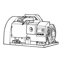
120/240-Volt (or 110/220-Volt,
100/200-Volt) Configurations—Figure 5-1
Circuit breaker must be a circuit breaker manufacturer
two-pole circuit breaker. Two single-pole circuit
breakers do not conform to NEC requirements when
supplying a 240-volt (or 220-volt) load. Thisis trueeven
if they are mechanically attached together. Leads L1
and L2 are different phases and must never be
connected together.
4 3 2 1
Stator Leads
LO
GRD.
L2
L1
LO (Neutral)
Line
Side
Factory
Two-Pole
Circuit
Breaker
Ground
Load
Side
120/240 Volt, 3 Wire
Figure 5-1.
Leads 60 Hz 50 Hz
L0-L1 120 volt 110 volt
L0-L2 120 volt 110 volt
L1-L2 240 volt 220 volt
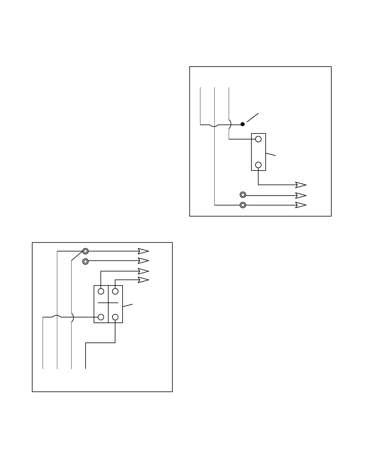
200-240-Volt
Configurations—Figure 5-2
This system uses a single-pole circuit breaker with
200-240 Volt, 2 Wire.
4 3 2 1
Stator Leads
LO
GRD.
L1
LO (Neutral)
Line
Side
Single-Pole
Circuit
Breaker
Ground
Load
Side
Tape to insulate
from ground
Figure 5-2.
Leads 60 Hz 50 Hz
L0-L1 Not used 200-240 volt