KEIHIN CARBURETOR
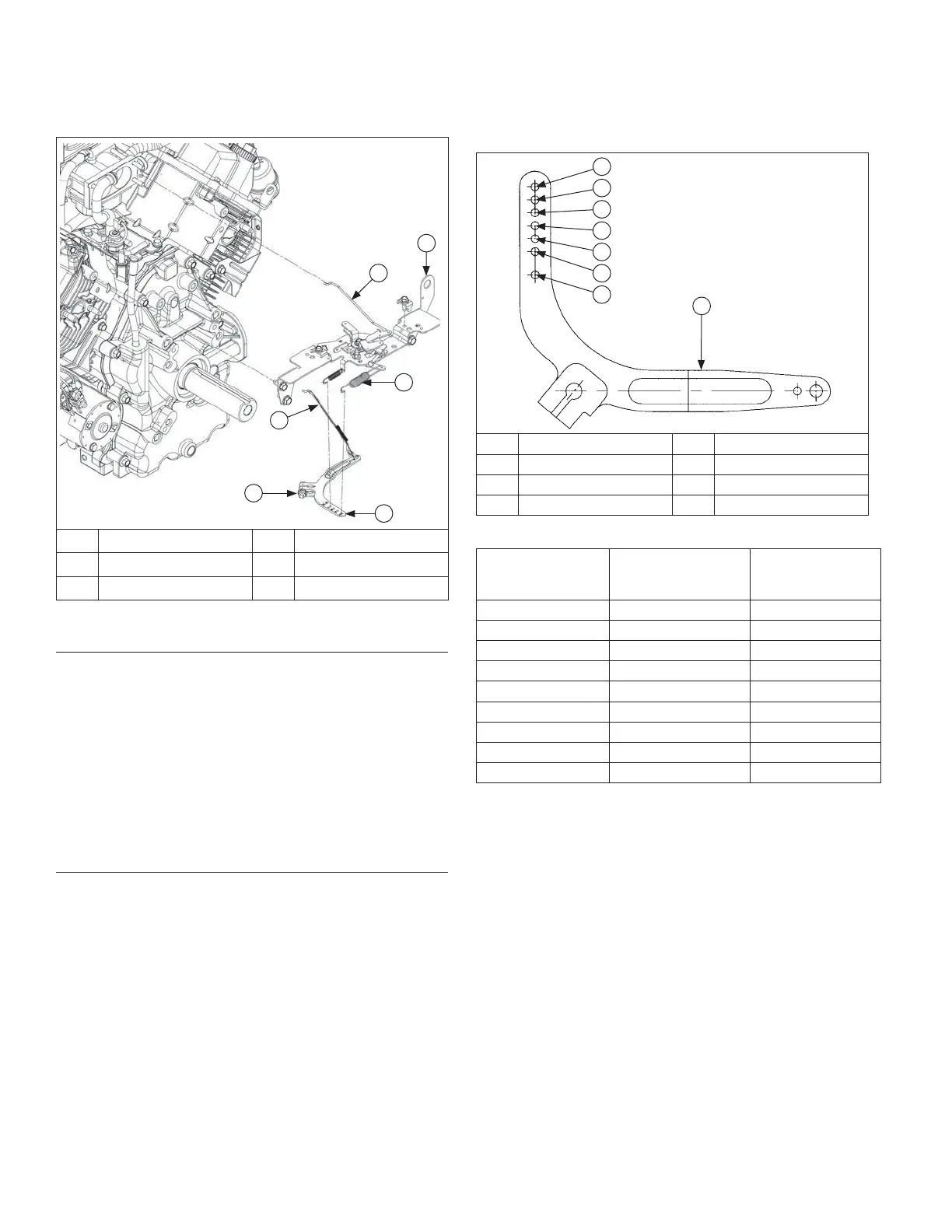
Governor Lever and Spring Details
Governor Lever Hole Position (6 mm)
H
A
G
F
E
D
C
B
A Governor Lever B Governed Idle Hole
C Hole 1 D Hole 2
E Hole 3 F Hole 4
G Hole 5 H Hole 6
6 mm Governor Lever and Hole Position/RPM Chart
High Idle RPM
Gov. Lever
Hole No.
Governor
Spring Color
Code
3801-4000 5 Clear
3601-3800 4 Clear
3451-3600 3 Clear
3301-3450 2 Clear
3101-3300 4 Purple
2951-3100 3 Purple
2800-2950 2 Purple
3750* 3 Clear
3150* 3 Purple
*5% Regulation (others 10%)
Control Bracket Components (Mechanical
Governor)
E
F
D
C
B
A
A Choke Linkage B Control Bracket
C Spring D Governor Lever
E Nut F Throttle Linkage
Install External Governor Controls (Mechanical
Governor)
1. Install governor lever onto governor cross shaft.
2. Make sure throttle linkage is connected to governor
lever and throttle lever on carburetor.
3. Move governor lever toward carburetor as far as it
will go (wide-open throttle) and hold in position.
4. Insert a nail into hole on cross shaft and rotate shaft
counterclockwise as far as it will turn, then torque
nut to 6.8 N·m (60 in. lb.).
5. Reconnect lead wire to fuel shut-off solenoid if
equipped.
Install Throttle & Choke Controls
1. Connect choke linkage (if equipped) to carburetor
and choke actuator lever.
2. Mount main control bracket, and air cleaner support
bracket (if used) to cylinder heads using four screws.
Torque screws to 10.7 N·m (95 in. lb.) into new
holes, or 7.3 N·m (65 in. lb.) into used holes.
3. Connect governor spring from main control bracket
to appropriate hole in governor lever as indicated in
applicable chart for Keihin carburetor or Nikki
carburetor. Note that hole positions are counted from
pivot point of governor lever.
Reassembly
118 24 690 06 Rev. PKohlerEngines.com
 Loading...