Electrical System
62 24 690 06 Rev. PKohlerEngines.com
ELECTRONIC IGNITION SYSTEMS
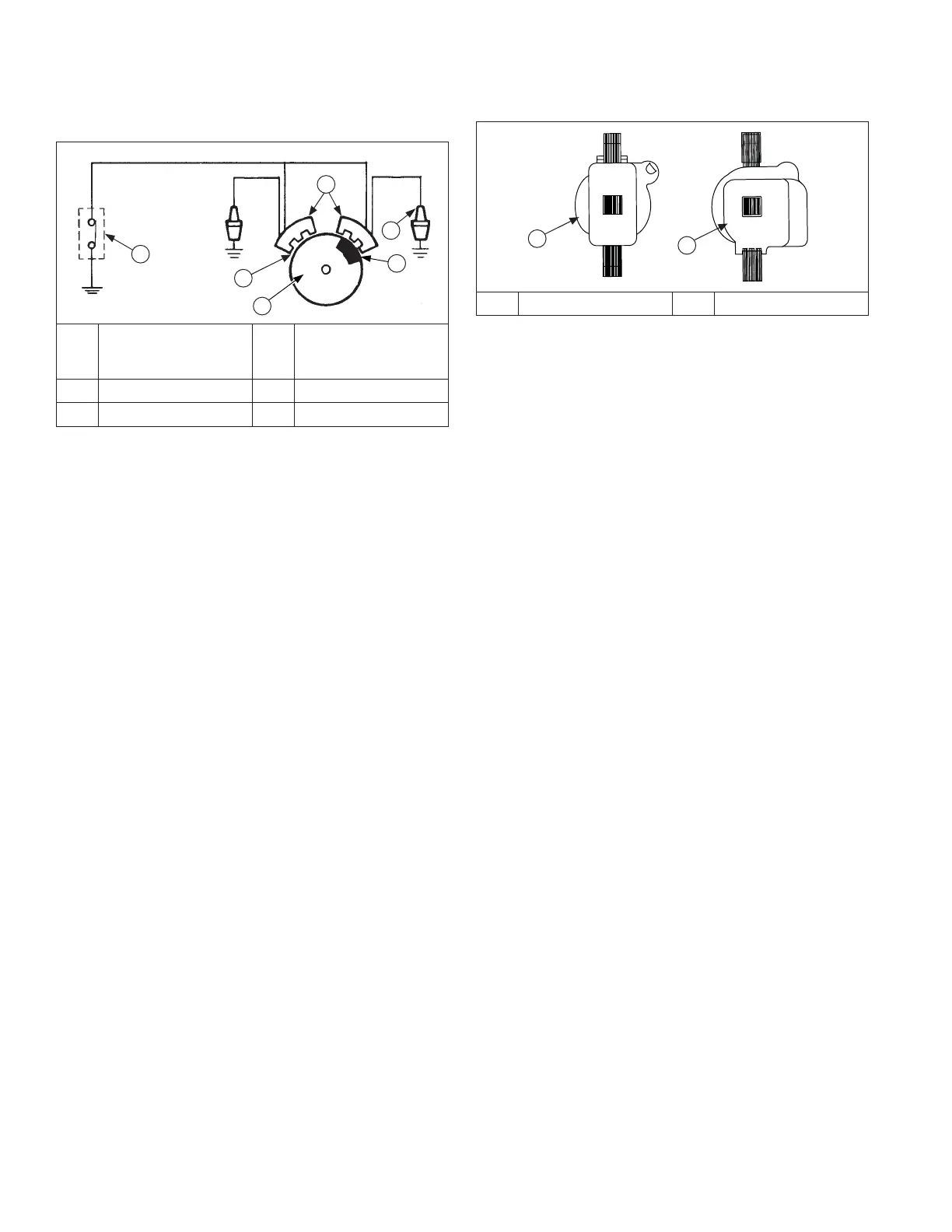
Ignition System Components
A
B
C
D
E
F
A
Kill Switch/
Off Position of
Key Switch
B Air Gap
C Flywheel D Magnet
E Spark Plug F Ignition Modules
There are 3 diff erent types of ignition systems used on
these engines. All systems use an ignition module which
energizes spark plug. Diff erence in systems is in way
ignition timing is triggered.
All ignition systems are designed to be trouble free for
life of engine. Other than periodically checking/replacing
spark plugs, no maintenance or timing adjustments
are necessary or possible. Mechanical systems do
occasionally fail or break down. Refer to Troubleshooting
to determine root of a reported problem.
Reported ignition problems are most often due to poor
connections. Before beginning test procedure, check
all external wiring. Be certain all ignition-related wires
are connected, including spark plug leads. Be certain all
terminal connections fi t snugly. Make sure ignition switch
is in run position.
CDI/MDI Ignition see pages 59-62.
Smart-Spark
TM
Ignition see pages 63-68.
DSAI Ignition see pages 69-71.
CDI/MDI Ignition Module Identifi cation
A
B
A CDI Ignition Module B MDI Ignition Module
These systems use a capacitive discharge (CD) coil.
With CDI fi xed timing, ignition timing and spark remains
constant regardless of engine speed. Timing of spark
is controlled by location of fl ywheel magnet group as
referenced to engine TDC. MDI adjustable timing uses
a digital microprocessor which is located in ignition
modules. Ignition timing varies depending upon engine
speed with this system.
A typical CDI/MDI ignition system consists of:
● 1 magnet assembly which is permanently affi xed to
fl ywheel.
● 2 electronic capacitive-discharge (CDI) or magnetic
discharge (MDI) ignition modules which mount on
engine crankcase.
● 1 kill switch (or key switch) which grounds modules to
stop engine.
● 2 spark plugs.
 Loading...