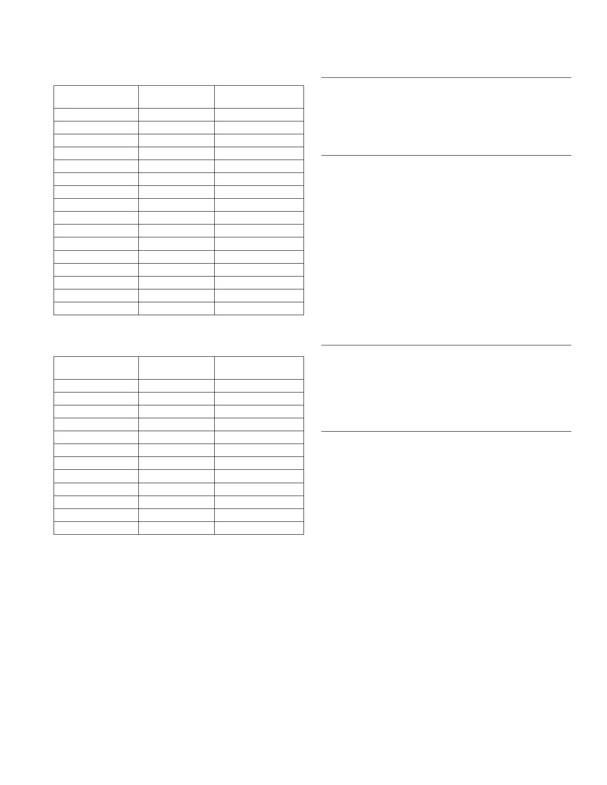
Governor Lever and Hole Position/RPM Chart for
CH680 Engines (No Throttle Stop)
High Idle RPM
Gov. Lever
Hole No.
Governor Spring
Color
3950-4000 4 Red
3800-3900 3 Purple
3750 3 Green
3650-3700 3 Red
3600 2 Orange
3550 2 Purple
3500 3 Clear
3450 2 Black
3300-3400 2 Red
3200-3250 1 Orange
3150 1 Black
3100 1 Blue
3050 1 Red
2850-3000 1 Clear
3750* 2 Orange
3150* 2 Clear
*5% Regulation (others 10%)
Governor Lever and Hole Position/RPM Chart for
CH730, CH740 Engines
High Idle RPM
Gov. Lever
Hole No.
Governor Spring
Color
3900-4000 4 Blue
3800-3850 3 Black
3600-3750 2 Orange
3550 3 Clear
3550 2 Red
3500 3 Blue
3450 2 Orange
3300-3400 2 Black
3200-3250 1 Red
3000-3100 1 Clear
3750* 23 Green
3150* 2 Clear
*5% Regulation (others 10%)
Install Oil Sentry
™
(if equipped)
1. Apply pipe sealant with Tefl on
®
(Loctite
®
PST
®
592™
or equivalent) to threads of Oil Sentry
™
switch and
install it into breather cover. Torque to 4.5 N·m
(40 in. lb.).
2. Connect wire lead (green) to Oil Sentry
™
terminal.
Install Idle Solenoid (if equipped)
1. Position roll pin in governor lever hole as noted in
disassembly. Position solenoid bracket assembly to
closure plate and secure with two screws. Make sure
screws and washer are in proper locations as noted
in disassembly.
2. Reinstall throttle linkage and linkage spring into
governor lever as noted in disassembly. Connect
bushing to throttle linkage.
3. Reinstall rear air cleaner bracket to cylinder heads.
Top screw on #2 cylinder also secures ground lead
ring terminal.
4. Connect governor spring to governor lever hole as
noted in disassembly. Other end of spring is in
speed control rod.
5. Connect fl ag terminals to idle solenoid.
Install Control Panel (if equipped)
1. Install panel to blower housing.
2. Connect throttle control cable or shaft.
3. Connect choke control cable to control bracket.
4. Connect Oil Sentry
™
indicator light wires.
Install Debris Shield and Control Cable Assembly (if
equipped)
1. Position debris shield and control lever assembly.
Start screws to hold in place.
2. Connect choke wire to lever on control bracket.
3. Secure choke wire to control bracket with cable
clamp.
Reassembly
12124 690 06 Rev. P KohlerEngines.com
 Loading...