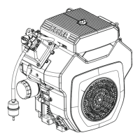
Install Valve Covers
Torque Sequence
1
2
3
4
NOTE: Do not scrape old RTV sealant (if used) off
sealing surface of cylinder head as this could
cause damage and result in leaks. Use of gasket
remover solvent (paint remover) is
recommended.
NOTE: Second fastener may secure fuel pump bracket
on earlier models.
Three valve cover designs have been used. First type
used a gasket and RTV sealant between cover and
sealing surface of cylinder head. Second type had a
black O-ring installed in a groove on underside of cover
and may have metal spacers in bolt holes. Latest design
uses a yellow or brown O-ring, with bolt hole spacers
molded in place. Tightening torque diff ers between
gasket and O-ring style covers. Kits are available for
converting to latest O-ring type covers. Diff erences are
pointed out in following installation steps.
1. If using gasket or sealant type cover, prepare sealing
surfaces of cylinder head and cover, refer to Tools
and Aids for approved sealants. Always use fresh
sealant. Using outdated sealant could result in
leakage. With O-ring type covers, make sure sealing
surfaces are clean.
2. Make sure there are no nicks or burrs on sealing
surfaces.
3. For covers requiring RTV sealant, apply a 1.5 mm
(1/16 in.) bead to sealing surface of both cylinder
heads, install a new cover gasket on each, then
apply a second bead of sealant on top surface of
gaskets. For O-ring type covers, install a new O-ring
in groove of each cover. Do not use gaskets or RTV
sealant.
4. Locate cover with oil fi ll neck on same side as
removed and install lifting strap in original position.
With O-ring type covers, position cover on cylinder
head. If loose spacers were used, insert a spacer in
each screw hole. On both types, install four screws
in each cover and fi nger tighten.
5. Torque valve cover fasteners to proper specifi cation
using sequence shown.
Torque Specifi cations-Covers
Gasket/RTV 3.4 N·m (30 in. lb.)
Black O-ring
w/shoulder screws
w/screws and spacers
5.6 N·m (50 in. lb.)
9.9 N·m (88 in. lb.)
Yellow or Brown O-ring
w/integral spacers 9.0 N·m (80 in. lb.)
Install Air Cleaner Assembly
Low-Profi le Air Cleaner
NOTE: Route fuel line in contour to avoid restriction.
1. Attach rubber breather hose to breather cover.
Connect fuel inlet line to carburetor and secure with
a clamp.
2. If equipped, carefully install evap hose fi tting into
bottom of air cleaner base.
3. Position a new gasket and air cleaner base while
carefully pulling loose end of rubber breather hose
through base until properly seated (collars sealed
against each side of base).
4. Secure air cleaner base and bracket using screws.
Position bracket with hole toward breather hose. Be
careful not to drop screws into carburetor. If a rear
air cleaner bracket is used, install two M5 screws
through rear of base. Torque three M6 screws to
6.2-7.3 N·m (55-65 in. lb.) and two rear M5 mounting
screws (when applicable) to 4.0 N·m (35 in. lb.).
5. Install breather hose in hole of bracket. If equipped,
install evap hose in other hole of bracket.
6. Install air cleaner components, refer to Air Cleaner/
Intake.
Heavy-Duty Air Cleaner
1. If equipped, place a new air cleaner base gasket on
carburetor and reinstall remote air cleaner adapter.
Install 2 screws and torque to 7.3 N·m (65 in. lb.).
Place a new adapter gasket on adapter. Make sure
holes in gasket are in proper location.
2. If equipped, route evap line through strap on bottom
of air cleaner support bracket and position air
cleaner and bracket assembly on engine.
3. Align air cleaner mounting bracket with valve cover
mounting holes and start screws. On two-barrel
carburetor models start two mounting screws into
top of intake manifold.
4. Check alignment of bracket and torque valve cover
screws as prescribed in Install Valve Covers. Torque
upper mounting screws into manifold (two-barrel
models only) to 9.9 N·m (88 in. lb.).
5. Secure adapter elbow to remote adapter with 2
screws. Torque screws to 7.3 N·m (65 in. lb.).
6. Connect air cleaner hose to adapter elbow or
adapter on carburetor and secure with a clamp.
Install and tighten hood onto air cleaner inlet.
7. Reconnect evap line to fi tting in adapter. Connect
breather hose to breather cover and fi tting on
adapter/elbow; position clamps to secure.
Reassembly
122 24 690 06 Rev. PKohlerEngines.com
 Loading...