10.1
Section 10
Reassembly
10
Section 10
Reassembly
General
NOTE: Make sure the engine is assembled using
all specifi ed torque values, tightening
sequences, and clearances. Failure to observe
specifi cations could cause severe engine wear
or damage. Always use new gaskets. Apply a
small amount of oil to the threads of critical
fasteners before assembly, unless a Sealant or
Loctite
®
is specifi ed or preapplied.
Make sure all traces of any cleaner are removed before
the engine is assembled and placed into operation.
Even small amounts of these cleaners can quickly
break down the lubricating properties of engine oil.
Check the closure plate, crankcase, cylinder heads,
and valve covers to be certain that all of the old gasket
material has been removed. Use gasket remover,
lacquer thinner, or paint remover to remove any
remaining traces. Clean the surfaces with isopropyl
alcohol, acetone, lacquer thinner, or electrical contact
cleaner.
Typical Reassembly Sequence
The following sequence is suggested for complete
engine reassembly. This procedure assumes that all
components are new or have been reconditioned, and
all component subassembly work has been completed.
The sequence may vary to accommodate options or
special equipment. Detailed procedures follow:
1. Install fl ywheel end oil seal.
2. Install li er feed chamber gaskets and cover.
3. Install fl ywheel end main bearing.
4. Install governor sha s, seal, and governor gear.
5. Install cranksha .
6. Install connecting rods with pistons and rings.
7. Install camsha .
8. Install closure plate main bearing and oil seal.
9. Install closure plate assembly.
10. Install oil pickup screen.
11. Install oil reservoir.
12. Check cranksha end play.
13. Install breather assembly.
14. Install hydraulic li ers.
15. Assemble and install cylinder heads.
16. Install push rods and rocker arms.
17. Install valve covers.
18. Install spark plugs.
19. Install oil fi lter adapter.
20. Install intake manifold.
21. Install oil fi lter housing assembly.
22. Install backing shroud assembly.
23. Install stator, wiring harness, and rectifi er-
regulator.
24. Install fl ywheel.
25. Install ignition modules.
26. Install outer cylinder baffl es.
27. Install oil cooler.
28. Install cooling fan and grass screen.
29. Install electric starter.
30. Install valley baffl es.
31. Install carburetor
32. Install governor lever.
33. Install control bracket and air cleaner assembly.
34. Install thro le and choke linkages.
35. Install Oil Sentry™
switch (if equipped).
36. Install blower housing and cylinder shrouds.
37. Install control panel (if equipped).
38. Install muffl er.
39. Install oil fi lter and add oil to crankcase.
40. Connect spark plug leads.
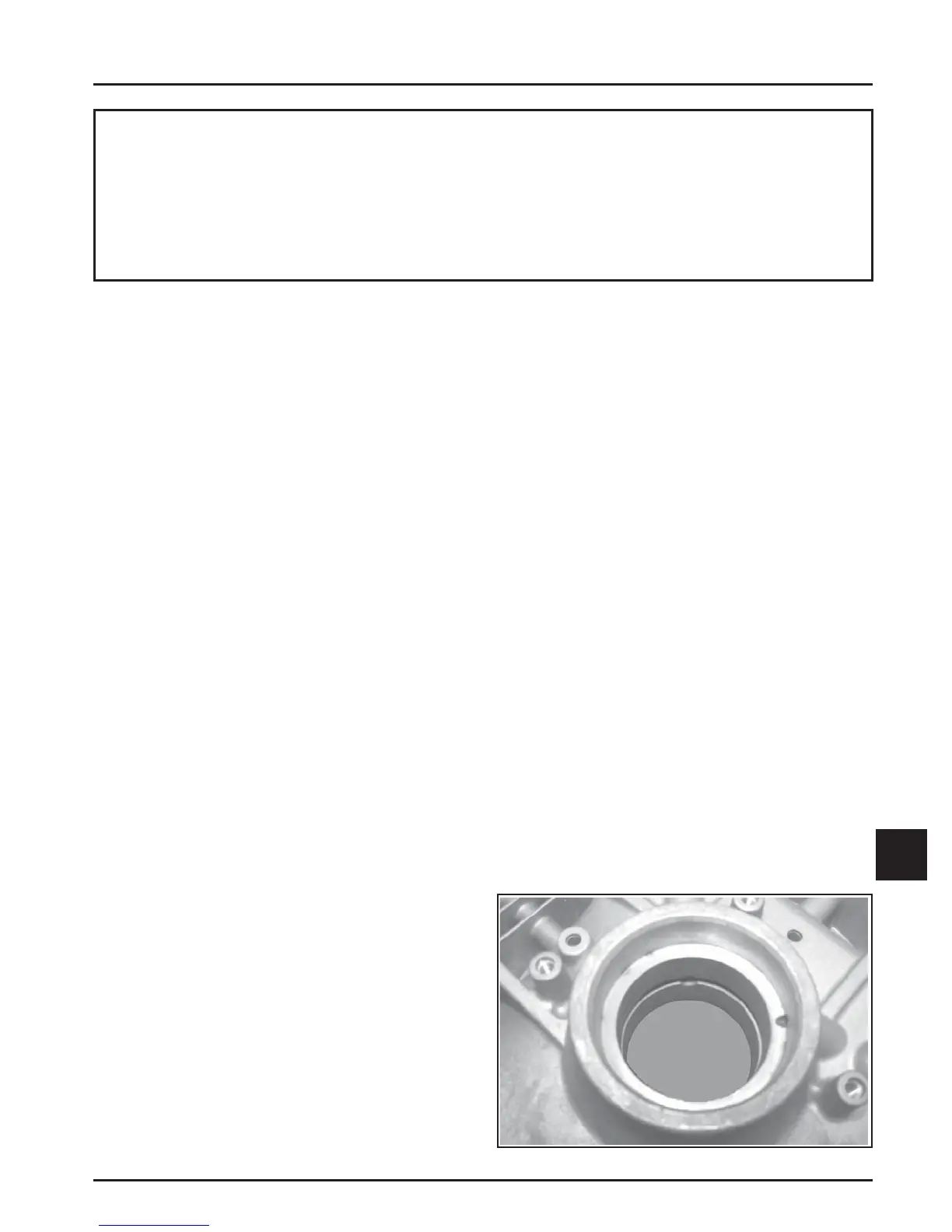
Install Flywheel End Oil Seal
1. Make sure that the seal bore of the crankcase is
clean and free of any nicks or burrs. See Figure
10-1.
Figure 10-1. Seal Bore of Crankcase.
 Loading...