10.25
Section 10
Reassembly
10
11, 5
4
3
2
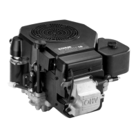
Figure 10-98. Torque Sequence for Air Cleaner
Mounting Nuts.
5. Connect the breather hose to the fi ing on the
outlet of the air cleaner and connect the fuel
solenoid lead.
6. Connect the formed vent hose to the air cleaner
housing and the vent port on the carburetor.
Install Throttle and Choke Linkages
If the individual thro le/choke lever control linkages
were disconnected during disassembly, reconnect
them based on the operating direction of the control
cables to be used.
On Control Levers:
Hole A is used for Outer Pull control cable actuation.
Hole B is used for Inner Pull control cable actuation.
See Figures 10-99 and 10-100.
1. Connect the choke linkage to the appropriate hole
in the choke lever and secure with the small clip.
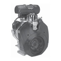
Linkages Connected Here
(A)
(A)
Throttle Control
Clamp Location
Choke Control
Clamp Location
Figure 10-99. Throttle/Choke Linkage Details for
Outer Pull Actuation.
2. Connect the thro le linkage to the appropriate
hole in the thro le lever and secure with the
small clip.
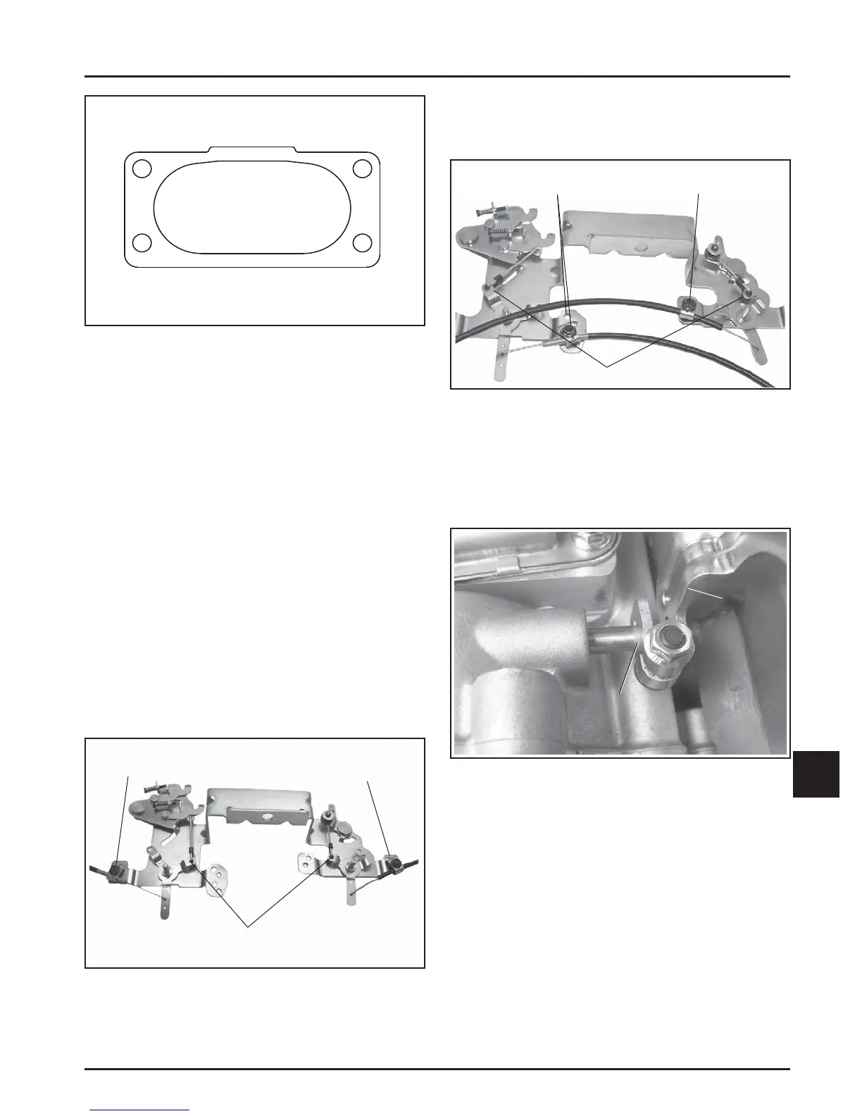
Linkages Connected Here
(B)
(B)
Throttle Control
Clamp Locations
Choke Control
Clamp Location
Figure 10-100. Throttle/Choke Linkage Details for
Inner Pull Actuation.
Adjusting Governor
1. Position the governor lever so the clamping area
is inboard but completely on the knurled area of
governor cross sha . See Figure 10-101.
Governor
Lever
Brushed/
Knurled
Area
Figure 10-101. Brushed/Knurled Area.
 Loading...