10.26
Section 10
Reassembly
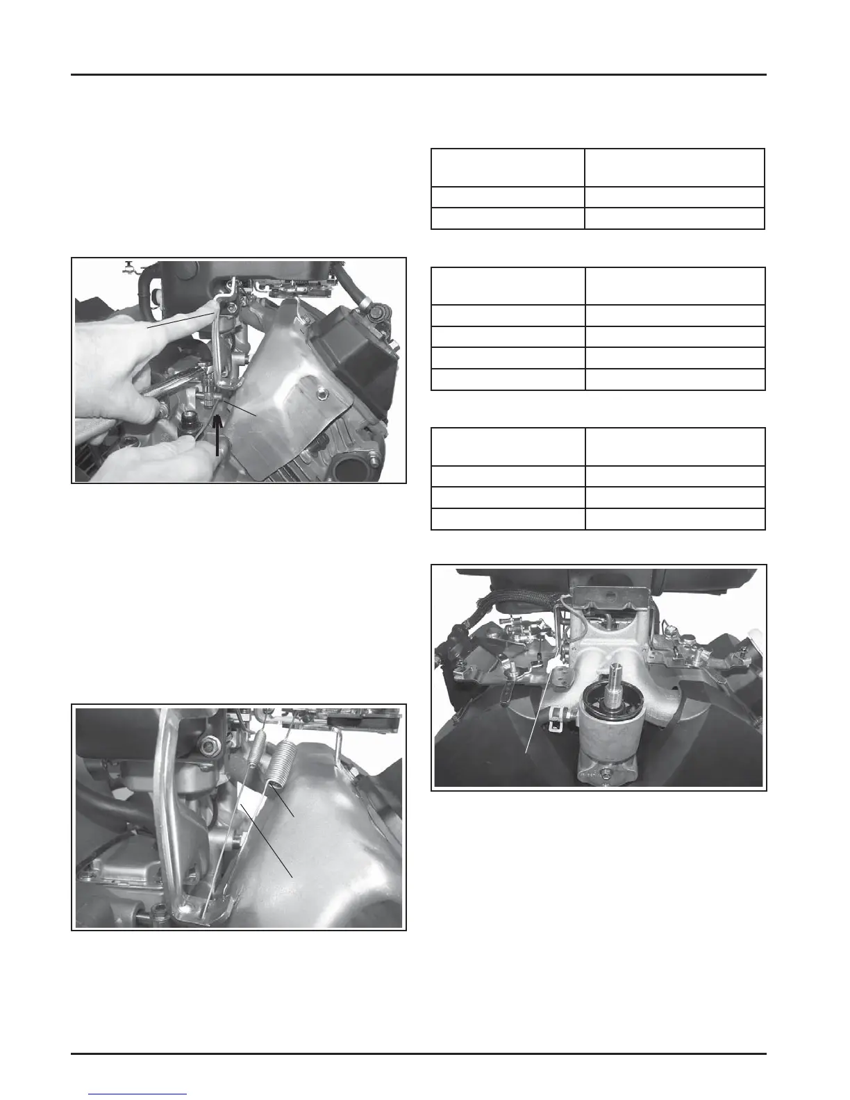
2. Move the governor lever toward the carburetor as
far as it will go (wide-open thro le) and hold in
position. See Figure 10-102.
3. Insert a long thin rod or tool into the hole on the
cross sha and rotate the sha clockwise (viewed
from the end) as far as it will turn, then torque
the hex nut to 7.3 N·m (65 in. lb.). See Figure 10-
102.
Lift/Rotate
Clockwise
Move and
Hold
Towards
Carburetor
Figure 10-102. Adjusting Governor.
4. Ensure that the correct color springs are used.
Connect the governor spring (with long looped
end), to the inner hole on the governor lever and
control bracket.
Connect the governed idle spring to the outer
governor lever hole and control bracket. The long
end of each spring must be toward the governor
lever. Make sure the springs do not contact the
valley baffl e. See Figure 10-103.
Governed Idle
Spring
Governor Spring
Figure 10-103. Governor Springs Installed.
Governor Spring/RPM Chart
CH940-CH1000
Governor Idle Spring
(Color)
High Speed (RPM)
Clear 1400-1625 RPM
Black 1626-1800 RPM
CH940, CH960, CH980
Governor Spring
(Color)
High Speed (RPM)
Red 3000-3150 RPM
Green 3151-3300 RPM
Green Patch 3301-3675 RPM
Red Patch 3676-3900 RPM
CH1000
Governor Spring
(Color)
High Speed (RPM)
Yellow Patch 3000-3150 RPM
Purple Patch 3151-3450 RPM
Purple 3451-3900 RPM
Figure 10-104. Governor Spring/RPM Chart.
Mounted Control Bracket
Figure 10-105. Control Bracket Assembly on
Engine.
Install Oil Sentry™ (If Equipped)
1. Apply pipe sealant with Tefl on
®
(Loctite
®
592™
PST
®
Thread Sealant or equivalent) to the threads
of the Oil Sentry™ switch and install it into the
1/8 in. port in the closure plate. See Figure 10-106.
Torque the switch to 10.1 N·m (90 in. lb.).
 Loading...