11.14
Section 11
Reassembly
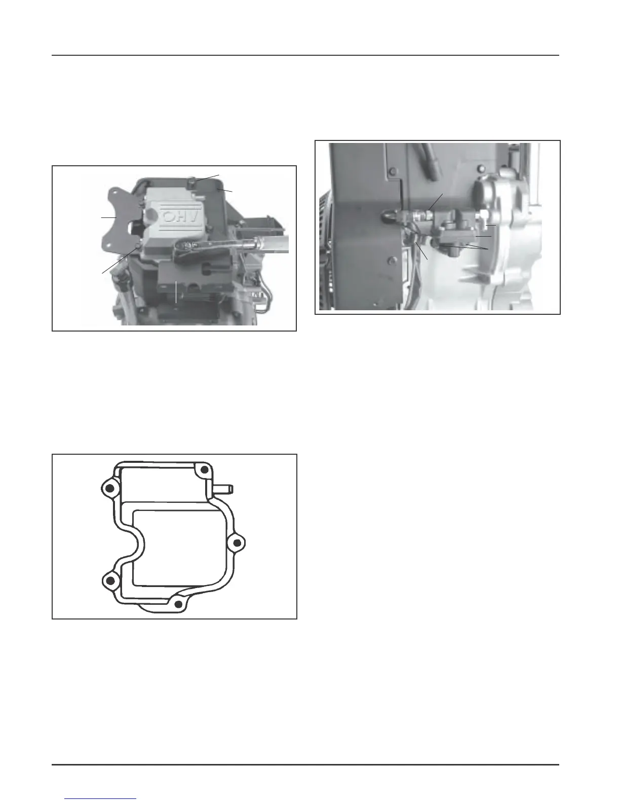
Figure 11-44. Installing Valve Cover. (Die Cast/
Aluminum Cover Shown).
4. Torque the screws in the sequence shown in
Figure 11-45, as follows:
Into new hole 10.7 N·m (95 in. lb.).
Into used hole 7.3 N·m (65 in. lb.).
Install Fuel Pump
1. Install the rubber line and two hose clamps to
the fuel pump end of the metal fuel line. Secure
the rubber fuel line to the metal fuel line with one
of the clamps. See Figure 11-46.
Figure 11-46. Installing Fuel Pump.
2. Install the gasket, fuel pump, and two hex flange
screws. Attach the wire harness clamp (if used)
onto the closest screw. Torque the screws as
follows:
Into new hole 9.0 N·m (80 in. lb.).
Into used hole 4.2-5.1 N·m (37-45 in. lb.).
3. Install the opposite end of the rubber line to the
outlet fitting of the fuel pump. Secure the fuel
line to the outlet fitting with the other hose
clamp.
Install Electric Starter
Electric Starter (Inertia Drive or Solenoid Shift)
1. Install the studs for starter into the crankcase (if
applicable and removed previously). The longer
set of threads must be out.
2. Install starter with spacer and ground lead (if
used) on the studs, or install starter using the
mounting bolts as originally equipped. See Figure
11-47.
Clamp
Outlet
Fuel Pump
Hex Flange
Screws
Inlet
1
2
3
4
5
Hex
Flange
Head
Screws
Lift Bracket
Cylinder
Head Baffle
Fuel Tank
Bracket
3. Install the valve cover, any attached mounting
brackets (muffler, fuel tank, and/or lift*) along
with any loose spacers (stamped steel cover) as
originally attached onto the cylinder head. Secure
with the five hex flange screws. See Figure 11-44.
*Lifting bracket must be toward the flywheel.
Figure 11-45. Valve Cover Torque Sequence.
Muffler Bracket
 Loading...


