8.29
Section 8
Electrical System and Components
8
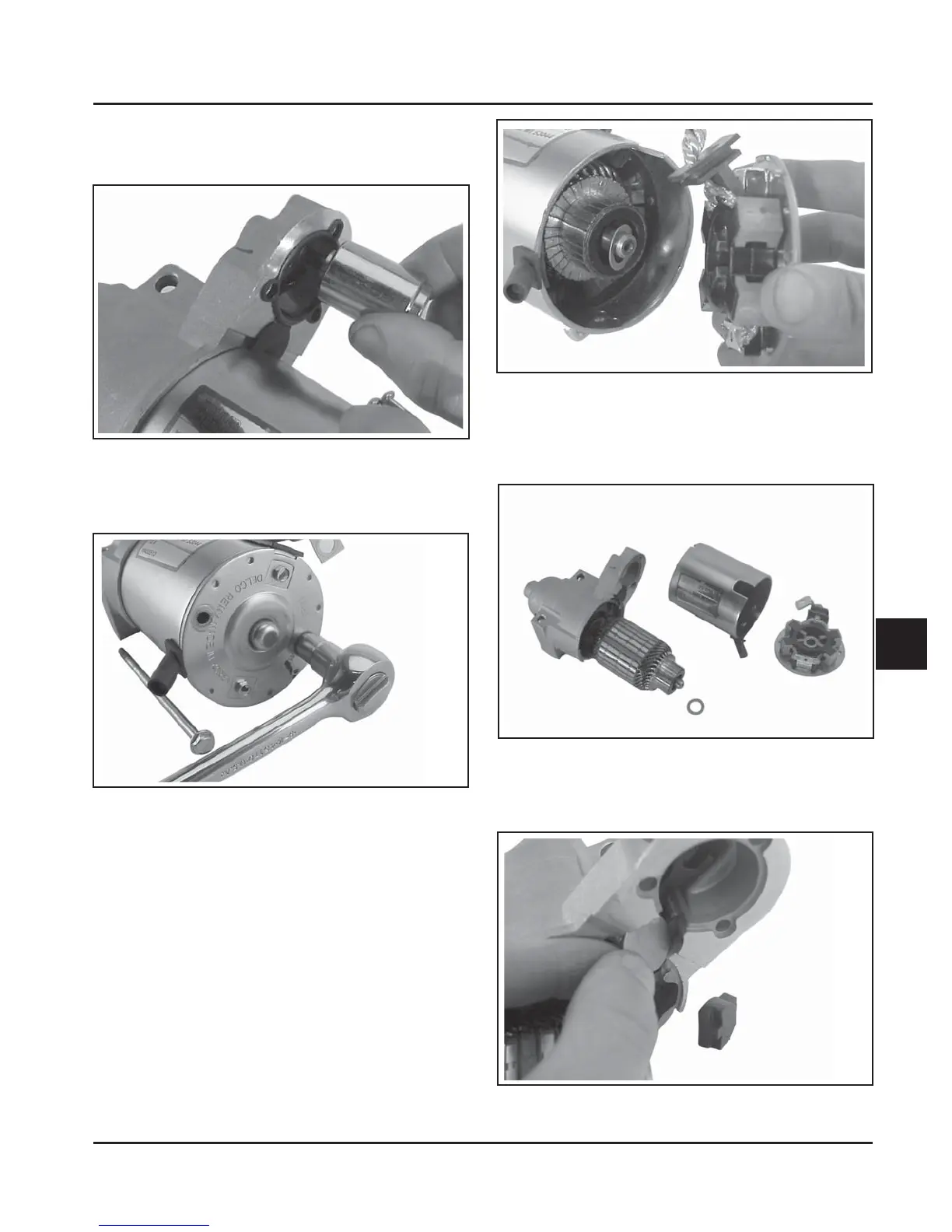
3. Lift and unhook the plunger assembly from the
drive lever. Remove the gasket from the recess in
the housing. See Figure 8-40.
Figure 8-40. Removing Plunger.
4. Remove the two thru (larger) bolts. See Figure
8-41.
Figure 8-41. Removing Thru Bolts.
5. Remove the commutator end plate assembly,
containing the brush holder, brushes, springs,
and locking caps. Remove the thrust washer from
inside the commutator end. See Figure 8-42.
Figure 8-42. Removing Commutator End Plate
Assembly.
6. Remove the frame from the armature and drive
end cap. See Figure 8-43.
Figure 8-43. Starter Frame Removed.
7. Remove the drive lever pivot bushing and
backing plate from the end cap. See Figure 8-44.
Figure 8-44.