9.9
Section 9
Disassembly
9
Figure 9-31. Removing Valve Cover.
Remove Ignition Modules
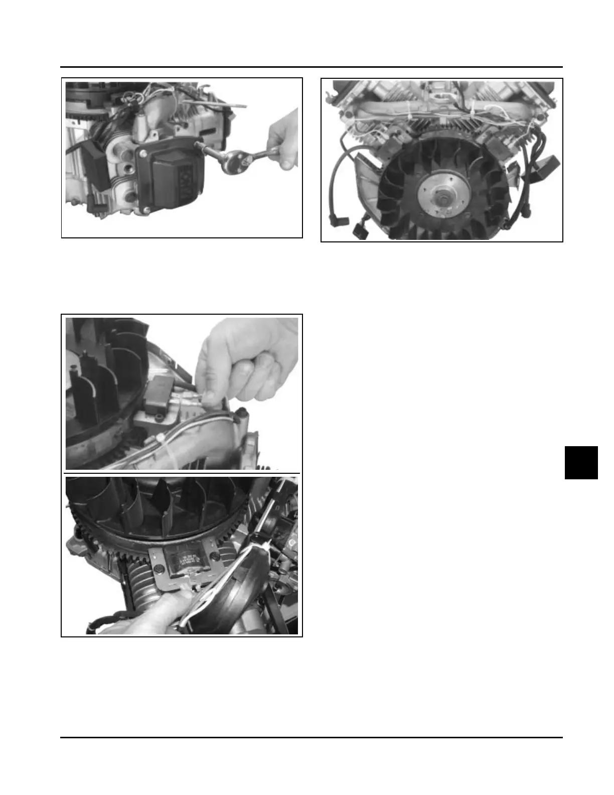
1. Disconnect the lead(s) from each ignition module.
See Figure 9-32.
Figure 9-33. Position of Ignition Modules.
3. Remove the mounting screws and ignition
modules. Note the position of the ignition
modules.
Remove Intake Manifold
1. Remove the four hex. flange screws securing the
intake manifold to the cylinder heads. Note which
screws hold the wiring clamps.
2. Remove the intake manifold and the intake
manifold gaskets (aluminum intake manifolds) or
O-Ring (plastic intake manifolds). See Figure
9-34.
3. Leave the wiring harness attached to the
manifold.
Figure 9-32. Disconnect Lead(s) from Ignition
Modules.
2. Rotate the flywheel so the magnet is away from
the modules. See Figure 9-33.
SMART-SPARK
™
Module Leads
Fixed Timing
Ignition Module
Kill Lead
Kohler Engine Parts Call K&T 606-678-9623 or 606-561-4983
www.mymowerparts.com