5B.12
Section 5B
EFI Fuel System
b. If the resistance is less than 1.0 M
ΩΩ
ΩΩ
Ω, the
sensor is bad, replace it.
5. With the oxygen sensor disconnected and
engine not running, disconnect the main
harness connector from the ECU and set the
meter to the Rx1 scale. Check the circuit
continuity as follows:
“24 Pin” (MSE 1.0) Plastic-Cased ECU:
Check for continuity from pin #15 of the ECU
connector (see page 5B.26) to the shell of the
oxygen sensor, and from pin #11 to the sensor
connector terminal of the main harness. Both
tests should indicate continuity.
“32 Pin” (MSE 1.1) Plastic-Cased ECU: Check
for continuity from pin #19 of the ECU connector
(see page 5B.29) to the shell of the oxygen
sensor, and from pin #20 to the sensor terminal
of the main harness. Both tests should indicate
continuity.
a. If there is no continuity displayed in either of
the tests, check the harness circuit for
breaks or damage, and the connections for
poor contact, moisture, or corrosion. If no
continuity was found in the first test, also
check for a poor/broken ground path back
through the exhaust system, engine, and
mounting (sensor is grounded through its
shell).
b. If continuity is indicated, go to step 6.
6. With the key switch in the ‘‘on/run’’ position,
using a high impedance voltmeter, check the
voltage from the wiring harness oxygen sensor
connector to the engine ground location. Look
for a steady voltage from 350-550 mv
(0.35 - 0.55 v).
a. If the voltage reading is not as specified,
move the black voltmeter lead to the
negative post of the battery, to be certain of
a good ground. If the voltage is still not
correct, the ECU is probably bad.
b. If the voltage readings are correct, clear the
fault codes and run the engine to check if
any fault codes reappear.
To Replace Oxygen Sensor:
1. Disconnect the oxygen sensor connector from
the wiring harness.
2. Loosen and remove the oxygen sensor from the
exhaust manifold/muffler assembly.
3. Apply anti-seize compound sparingly to threads
of new oxygen sensor, if none already exists.
DO NOT get any on the tip as it will contaminate
the sensor. Install sensor and torque to
50-60 N·m (37-44 ft. lb.).
4. Reconnect the lead to the wiring harness
connector. Make sure it can not contact hot
surfaces, moving parts, etc.
5. Test run the engine.
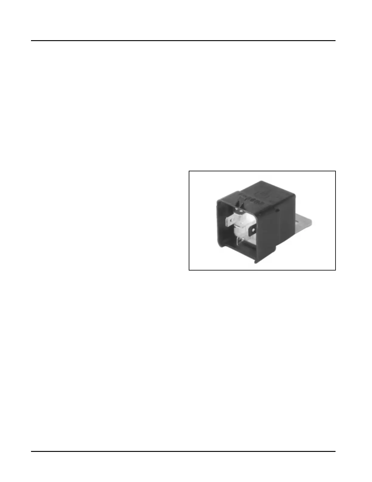
Electrical Relay
Figure 5B-11. Electrical Relay.
General
The electrical relay is used to supply power to the
injectors, coil, and fuel pump. When the key switch is
turned “on” and all safety switch requirements met, the
relay provides 12 volts to the fuel pump circuit,
injectors, and ignition coils. The fuel pump circuit is
continuously grounded, so the pump is immediately
activated and pressurizes the system. Activation of the
ignition coils and fuel injectors is controlled by the
ECU, which grounds their respective ground circuits at
the proper times.
Service
A malfunctioning relay can result in starting or
operating difficulties. The relay and related wiring can
be tested as follows.
1. Disconnect the relay connector plug from the
relay.
Kohler Engine Parts Call K&T 606-678-9623 or 606-561-4983
www.mymowerparts.com