9.11
Section 9
Disassembly
9
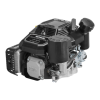
Figure 9-37. Removing Cylinder Head.
4. Remove the lifters from the lifter bores. Use
hydraulic lifter tool (SPX Part No. KO1044). Do
not use a magnet to remove lifters. Mark the
lifters by location, as either intake or exhaust, and
cylinder 1 or 2. Hydraulic lifters should always be
reinstalled in the same position. See Figure 9-38.
Figure 9-38. Removing Hydraulic Lifters.
Disassemble Cylinder Heads
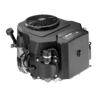
1. Remove the two hex. flange screws, rocker arm
pivots and rocker arms from the cylinder head.
See Figure 9-39.
Figure 9-39. Removing Rocker Arm.
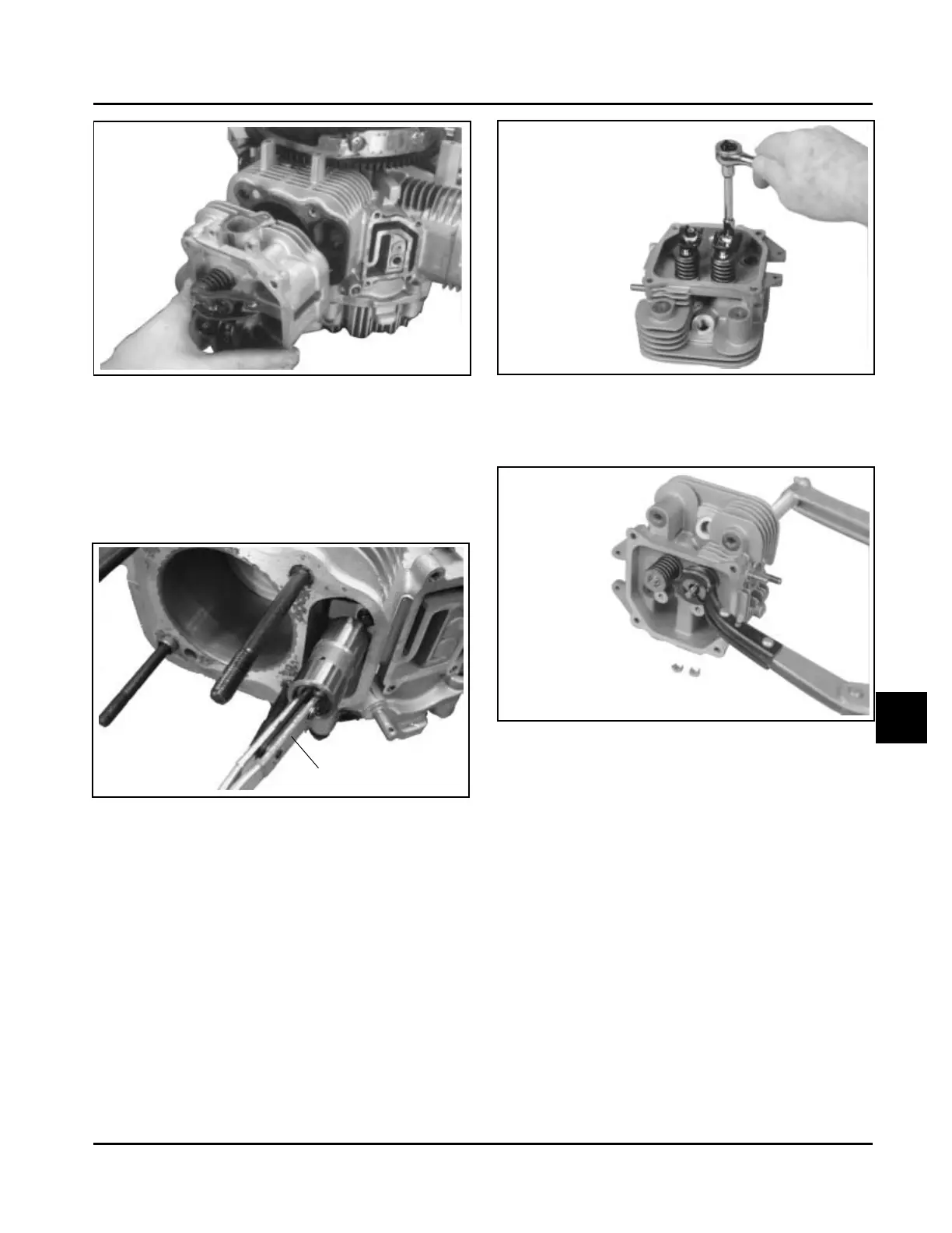
2. Compress the valve springs using a valve spring
compressor. See Figure 9-40.
Hydraulic Lifter Tool
Figure 9-40. Removing Valves with Valve Spring
Compressor.
3. Once the valve spring is compressed, remove the
following items. See Figures 9-41 and 9-42:
• Valve spring keepers
• Valve spring retainers
• Valve springs
• Valve spring caps
• Intake and exhaust valves (mark position)
• Valve stem seal (intake valve only)
Kohler Engine Parts Call K&T 606-678-9623 or 606-561-4983
www.mymowerparts.com