11.20
Section 11
Reassembly
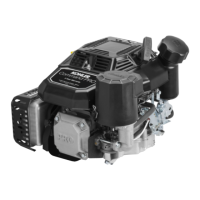
Figure 11-69. Installing External Governor Controls.
3. Move the governor lever toward the carburetor as
far as it will go (wide-open throttle) and hold in
position.
4. Insert a nail into the hole on the cross shaft and
rotate the shaft counterclockwise as far as it will
turn, then torque the hex. nut to 6.8 N·m
(60 in. lb.).
Install External Governor Controls
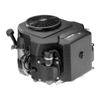
1. Install the governor lever onto the governor cross
shaft. See Figure 11-68.
Figure 11-68. Install Governor Lever to Shaft.
2. Make sure the throttle linkage is connected to the
governor lever and the throttle lever on the
carburetor. See Figure 11-69.
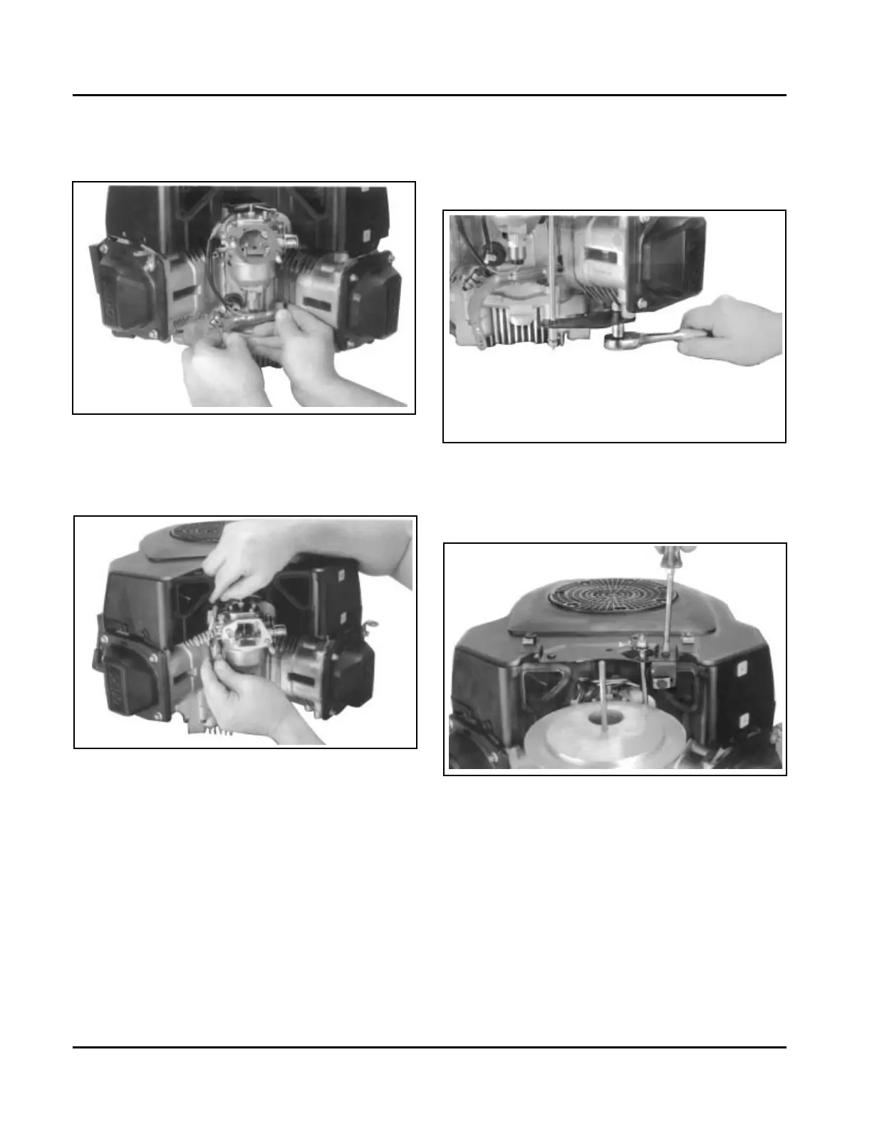
Figure 11-71. Installing Control Panel.
8. Assemble the throttle control shaft to the control
bracket.
9. Assemble the choke control to the control bracket.
10. Connect the Oil Sentry™ Indicator light wires.
Attach governor spring to governor lever. See
Figure 11-72 and appropriate charts on pages
11.22 through 11.24.
Figure 11-70. Installing Lower Support Control
Bracket.
7. Install control panel to the blower housing if
removed previously. See Figure 11-71.
5. Reconnect the lead wire to the fuel shut-off
solenoid if so equipped.
6. Install the lower support control bracket if equipped
with a control panel. See Figure 11-70
Kohler Engine Parts Call K&T 606-678-9623 or 606-561-4983
www.mymowerparts.com
 Loading...