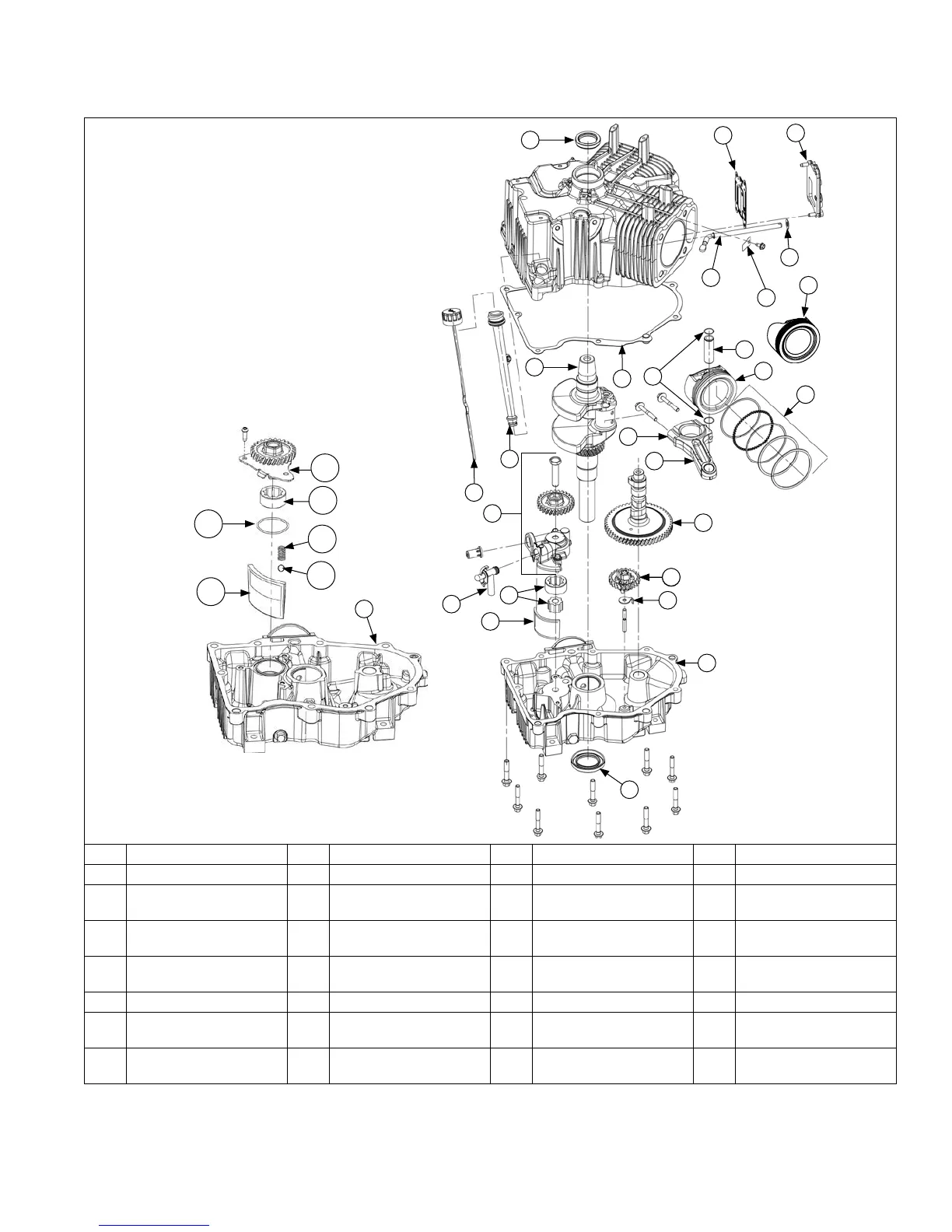
Breather/Oil Pan/Oil Reservoir/Piston Components
K
L
V
C
A
J
W
P
Q
R
I
N
U
T
S
D
E
X
F
C
B
M
G
H
O
J
Y
Z
AA
AB
AC
AD
AE
AF
A Oil Fill/Dipstick B Dipstick Tube C Oil Seal D Breather Gasket
E Breather Cover F Flat Washer G Breather Reed H Governor Cross Shaft
I Oil Pan Gasket J Governor Gear K
Locking Tab Thrust
Washer
L Oil Screen (Style A)
M Gerotor Gear (Style A) N
Oil Pick-Up Tube
(Style A)
O
Oil Pump Assembly
(Style A)
P Piston Pin
Q Piston (Style A) R Piston Ring Set S Piston Ring Retainer T
Connecting Rod End
Cap
U Connecting Rod V Crankshaft W Camshaft X Piston (Style B)
Y Oil Pan (Style A) Z Oil Pan (Style B) AA
Oil Pump Assembly
(Style B)
AB
Outer Gerotor Gear
(Style B)
AC
Oil Pump Cover O-ring
(Style B)
AD Spring (Style B) AE Ball (Style B) AF Oil Screen (Style B)
Reassembly
7524 690 07 Rev. H KohlerEngines.com