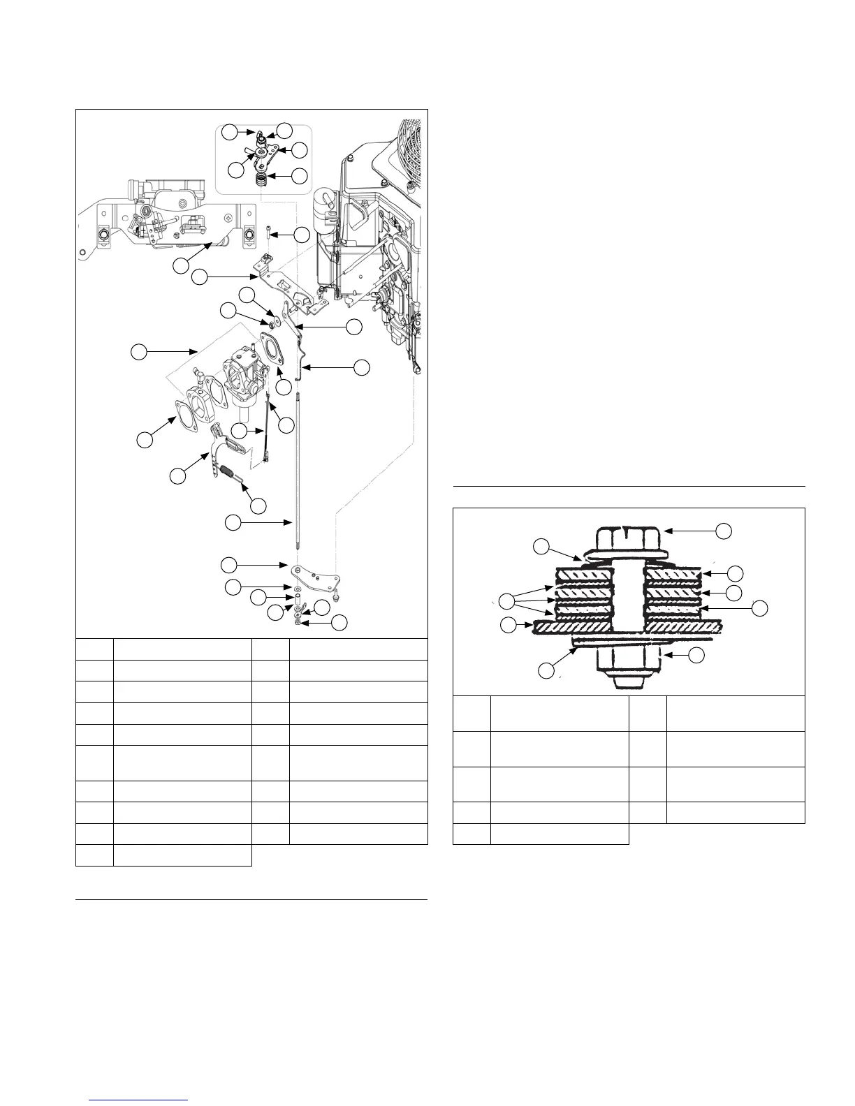
Control Panel Components
D
F
D
I
J
P
C
R
N
M
G
H
Q
B
E
S
L
A
B
C
C
K
C
L
B
O
A Nut B Lock Nut
C Flat Washer D Control Bracket
E Carburetor F Air Cleaner Gasket
G Governor Lever H Governor Spring
I Throttle Shaft J Bracket
K Spacer L
Throttle Control
Lever
M Linkage Spring N Throttle Linkage
O Carburetor Gasket P Choke Linkage
Q Choke Lever R Screw
S Throttle Shaft Spring
Install External Governor Controls
1. Install governor lever onto governor cross shaft.
2. Make sure throttle linkage is connected to governor
lever and throttle lever on carburetor.
Two-barrel carburetor models: Move control panel
into position on blower housing and connect choke
linkage into bushing/lever from backside. Make
certain that control shaft offset is back and towards
cylinder side 2. Connect throttle linkage and spring
to governor lever.
3. Move governor lever toward carburetor as far as it
will go (wide-open throttle) and hold in position.
4. Insert a long thin rod or tool into hole on cross shaft
and rotate shaft counterclockwise (viewed from end)
as far as it will turn, then torque nut to 6.8 N·m (60
in. lb.).
5. Reconnect lead wire to fuel shut-off solenoid (if
equipped).
6. Install lower support control bracket (if equipped with
a control panel).
7. Secure control panel to blower housing with screws
(if not equipped with heavy-duty air cleaner).
8. Assemble throttle control shaft to control bracket.
9. Assemble choke control to control bracket.
10. Connect Oil Sentry
™
Indicator light wires. Attach
governor spring to governor lever. See appropriate
charts.
Install Throttle and Choke Controls
Throttle and Choke Components
E
I
A
F
C
G
H
B
D
A Choke Lever B
Throttle Control
Lever
C
Throttle Actuator
Lever
D Lock Nut
E Choke Return Spring F
Speed Control
Bracket
G Flat Washer(s) H Wave Washer
I Screw
1. One-Barrel Carburetor Models: Connect choke
linkage to carburetor and choke actuator lever.
2. One-Barrel Carburetor Models: Install standard
throttle control bracket and air cleaner support
bracket (if used) to cylinder heads using screws.
Torque screws to 10.7 N·m (95 in. lb.) into new
holes, or 7.3 N·m (65 in. lb.) into used holes.
3. Connect governor spring from throttle control bracket
to appropriate hole in governor lever, as indicated in
applicable chart. Note that hole positions are
counted from pivot point of governor lever.
Reassembly
8524 690 07 Rev. H KohlerEngines.com