6324 690 01 Rev. K KohlerEngines.com
EFI SYSTEM-BOSCH
2. For plastic-cased ECU’s below 24 584 28-S, system
can be primed by manually cycling fuel pump.
a. Turn key switch to “ON/RUN” position. Fuel pump
will run for about three seconds and stop. Turn
switch off and back on to restart fuel pump.
Repeat this procedure until fuel pump has cycled
fi ve times, then start engine.
3. System can also be primed similar to relieving
pressure.
a. Connect pressure gauge as described above for
relieving fuel pressure. Depress and hold release
button and crank engine until air is purged and
fuel is visible in discharge tube. If fuel is not
visible after 10 seconds, stop cranking and allow
starter to cool for 60 seconds.
Priming Without a Test Valve in Fuel Rail
NOTE: Number of cranking intervals necessary will
depend on individual system design, and/or
when system has been disassembled.
1. Crank engine in 10-15 second intervals, allowing a
60 second cool-down period between cranking
intervals, until engine starts.
ELECTRICAL COMPONENTS
Three different styles of ECU’s have been utilized in EFI
production. First style is easily identifi ed by its metal
case with large 35 pin connector block, and also as MA
1.7. Second and third styles have plastic cases, but
are smaller in overall size. These have either a 24 pin
or 32 pin connector block and identifi ed as MSE 1.0
or MSE 1.1 respectively. Basic function and operating
control remains same between three, however, due to
differences in internal circuitry as well as wiring harness,
none of ECU’s are interchangeable. Certain individual
service/troubleshooting procedures also apply, where
applicable, they are covered individually as: “35 Pin”
(MA 1.7) Metal-Cased ECU, “24 Pin” (MSE 1.0) Plastic-
Cased ECU, or “32 Pin” (MSE 1.1) Plastic-Cased ECU.
Never attempt to disassemble ECU. It is sealed to
prevent damage to internal components. Warranty is
void if case is opened or tampered with in any way.
All operating and control functions within ECU are
preset. No internal servicing or readjustment may
be performed. If a problem is encountered, and you
determine ECU to be faulty, contact your source
of supply. Do not replace ECU without factory
authorization.
Relationship between ECU and throttle position sensor
(TPS) is very critical to proper system operation. If TPS
or ECU is changed, or mounting position of TPS is
altered, applicable “TPS Initialization Procedure” must
be performed to restore synchronization.
Engine speed sensor is a sealed, non-serviceable
assembly. If “Fault Code” diagnosis indicates a problem
within this area, check and test as follows.
1. Check mounting and air gap of sensor. It must be
1.5 mm ± 0.25 mm (0.059 ± 0.010 in.).
2. Inspect wiring and connections for damage or
problems.
3. Make sure engine has resistor type spark plugs.
4. Disconnect main harness connector from ECU.
5. Connect an ohmmeter between designated pin
terminals in plug:
“35 Pin” (MA 1.7) Metal-Cased ECU: #3 and
#21 pin terminals.
“24 Pin” (MSE 1.0) Plastic-Cased ECU: #9 and
#10 pin terminals.
“32 Pin” (MSE 1.1) Plastic-Cased ECU: #9 and
#10 pin terminals.
See page 26 according to ECU style. A resistance
value of 750-1000 at room temperature (20°C,
68°F) should be obtained. If resistance is correct,
check mounting, air gap, toothed ring gear (damage,
runout, etc.), and fl ywheel key.
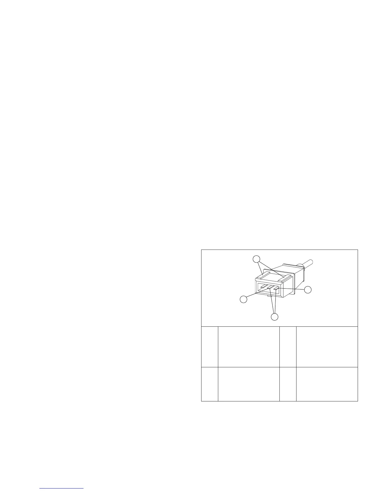
6. Disconnect speed sensor connector from wiring
harness. It is connector with one heavy black lead.
Viewing connector as shown (dual aligning rails on
top), test resistance between terminals indicated. A
reading of 750-1000 should again be obtained.
7. If resistance is incorrect, remove screw securing
sensor to mounting bracket and replace sensor.
a. If resistance in step 5 was incorrect, but
resistance of sensor alone was correct, test main
harness circuits between sensor connector
terminals and corresponding pin terminals in main
connector. Correct any observed problem,
reconnect sensor, and perform step 5 again.
Speed Sensor Circuit
A
D
C
B
A
Corresponds
To #3 (Metal-Cased
ECU) or #10
(Plastic-Cased
ECU) In Main
Connector.
B Dual Aligning Rails
C
Corresponds To #21
(Metal-Cased ECU)
or #9 (Plastic-Cased
ECU) In Main
Connector.
D Test Terminals