10.6
Section 10
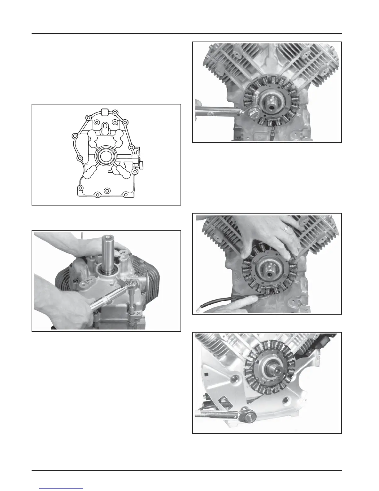
Reassembly
Figure 10-18. Torquing Stator Screws.
4. Route the stator leads in the crankcase channel,
then install the backing plate. Secure using the
four hex fl ange screws. See Figures 10-19 and
10-20. Torque the screws to 10.7 N·m (95 in. lb.)
into new holes or 7.3 N·m (65 in. lb.) into used
holes.
Figure 10-20. Installing Backing Plate.
Figure 10-19. Route Stator Leads in Groove.
Figure 10-16. Closure Plate Fastener Torque
Sequence.
10
6
2
9
7
3
1
8
4
5
6. Install the ten hex fl ange screws securing the
closure plate to the crankcase. Torque fasteners in
the sequence shown in Figure 10-16 to 25.6 N·m
(227 in. lb.). One of the ten mounting screws has
a thread sealant patch. This screw is typically
installed in the #10 hole shown in Figure 10-16.
Reapply pipe sealant with Tefl on
®
(Loctite
®
592
™
PST
®
Thread Sealant or equivalent).
Figure 10-17. Torquing Closure Plate Fasteners.
Install Stator and Backing Plate
1. Apply pipe sealant with Tefl on
®
(Loctite
®
592
™
PST
®
Thread Sealant or equivalent) to the stator
mounting holes.
2. Position the stator aligning the mounting holes
so that the leads are at the bo om, towards the
crankcase.
3. Install and torque the two hex fl ange screws to
6.2 N·m (55 in. lb.) into new holes or 4.0 N·m
(35 in. lb.) into used holes. See Figure 10-18.