10.8
Section 10
Reassembly
Figure 10-26. Applying Camshaft Lubricant to
Bottom of Lifters.
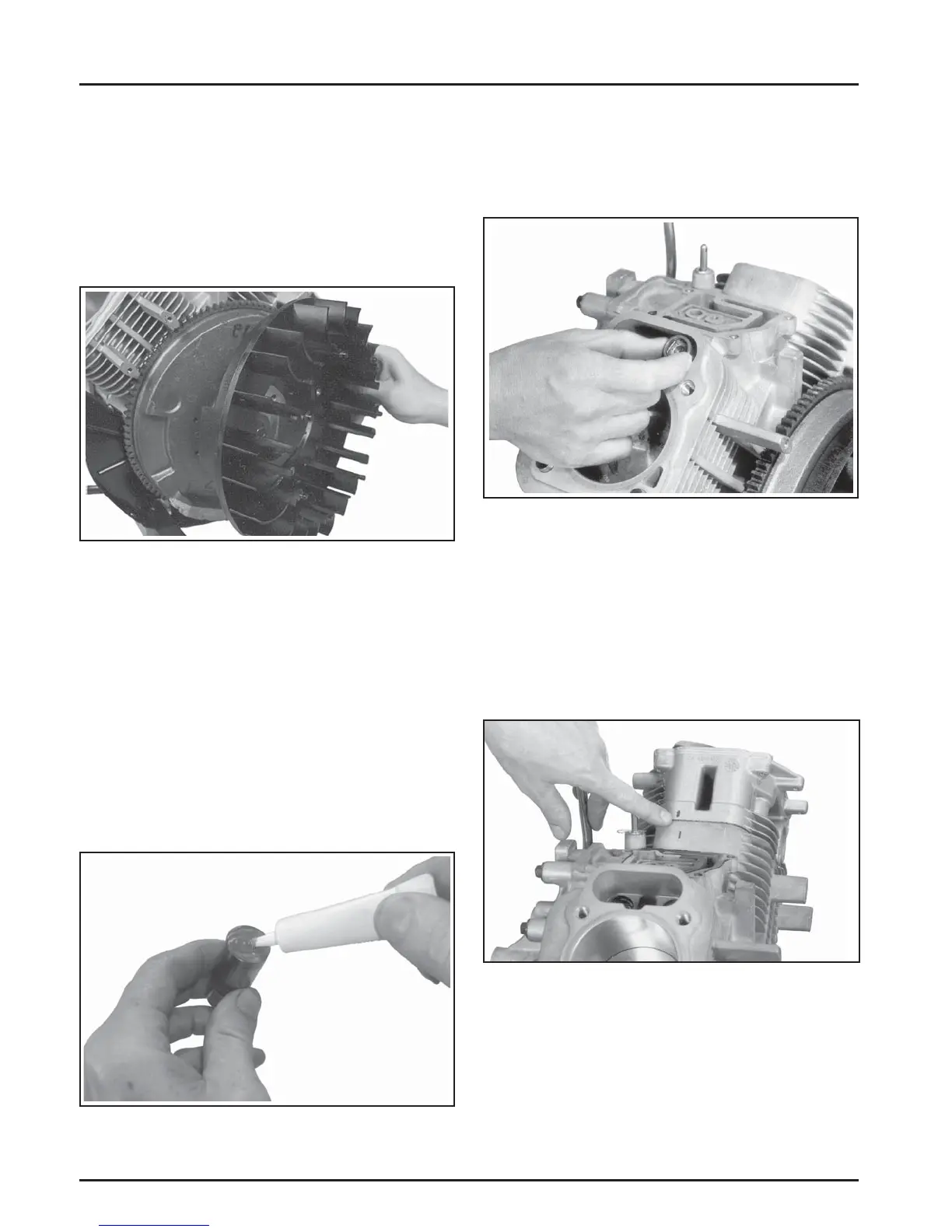
3. Note the mark or tag identifying the hydraulic
li ers as either intake or exhaust and cylinder
1 or cylinder 2. Install the hydraulic li ers into
their appropriate location in the crankcase. Do
not use a magnet. See Figure 10-27.
Figure 10-25. Installing Fan on Flywheel.
2. Torque the screws to 9.9 N·m (88 in. lb.).
Install Hydraulic Lifters and Cylinder
Heads
Install Hydraulic Lifters
1. See Servicing Hydraulic Li ers in Section 9 for
li er preparation (bleed down) procedures.
2. Apply camsha lubricant (see Section 2) to the
bo om surface of each li er. See Figure 10-26.
Lubricate the hydraulic li ers and the li er bores
in the crankcase with engine oil.
Figure 10-27. Installing Hydraulic Lifters.
NOTE: Hydraulic li ers should always be
installed in the same position as before
disassembly. The exhaust li ers are
located on the output sha side of
the engine while the intake li ers are
located on the fan side of the engine. The
cylinder numbers are embossed on the
top of the crankcase and each cylinder
head. See Figure 10-28.
Figure 10-28. Match Numbers on Crankcase and
Head.
Valve Stem Seals
These engines use valve stem seals on the intake
valves and on the exhaust valves. Always use a new
seal whenever the valve is removed or if the seal is
deteriorated or damaged in any way. Never reuse an
old seal. Figure 10-29.
Install Flywheel Fan
1. Install the fan onto the fl ywheel using the four
hex fl ange screws (engines with plastic grass
screen). Engines with a metal grass screen will
leave the fan loosely assembled.
NOTE: Position the locating tabs on the back
of the fan in the locating holes of the
fl ywheel. See Figure 10-25.