5.9
Section 5
EFI Fuel System
5
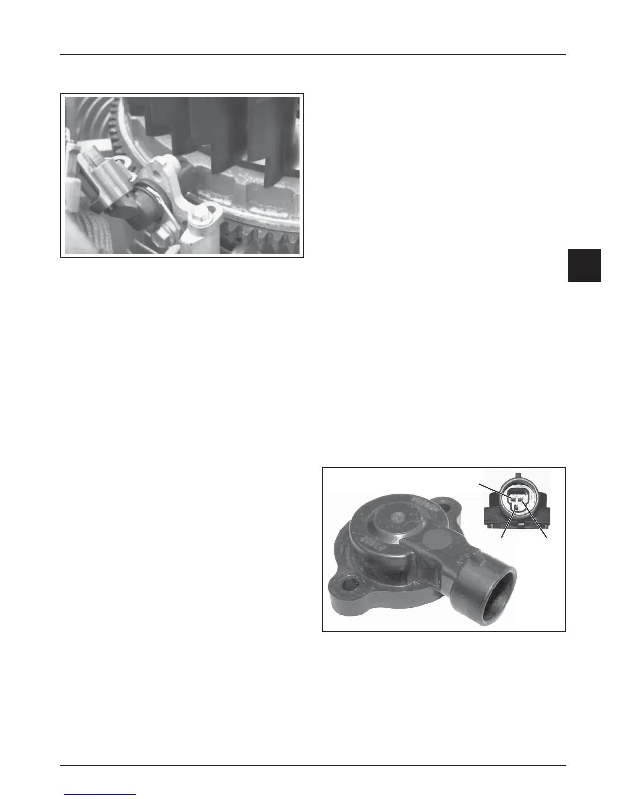
Figure 5-3. Crankshaft Position Sensor.
General
The cranksha position sensor is essential to
engine operation; constantly monitoring the
rotation and speed (RPM) of the cranksha .
There are 23 consecutive teeth cast into the
fl ywheel. One tooth is missing and is used to
reference the cranksha position for the ECU. The
inductive cranksha position sensor is mounted
0.20-0.70 mm (0.008-0.027 in.) from the fl ywheel.
During rotation, an AC voltage pulse is created within
the sensor for each passing tooth. The ECU calculates
engine speed from the time interval between the
consecutive pulses. The gap from the missing tooth
creates an interrupted input signal, corresponding
to specifi c cranksha position near BDC for cylinder
#1. This signal serves as a reference for the control
of ignition timing by the ECU. Synchronization of
the inductive speed pickup and cranksha position
takes place during the fi rst two revolutions each
time the engine is started. The sensor must be
properly connected at all times. If the sensor becomes
disconnected for any reason, the engine will quit
running.
Service
The cranksha position sensor is a sealed, non-
serviceable assembly. If Fault Code diagnosis indicates
a problem within this area, test and correct as follows.
1. Check the mounting and air gap of the sensor. It
must be 0.20-0.70 mm (0.008-0.027 in.).
2. Inspect the wiring and connections for damage or
problems.
3. Make sure the engine has resistor type spark
plugs.
4. Disconnect the Black connector from the ECU.
5. Connect an ohmmeter between the #4 and #13 pin
terminals. A resistance value of 325-395 at room
temperature (20°C, 68°F) should be obtained. If
resistance is correct, check the mounting, air gap,
fl ywheel teeth (damage, run-out, etc.), and
fl ywheel key.
6. Disconnect the cranksha position sensor
connector from the wiring harness. Test resistance
between the terminals. A reading of 325-395
should again be obtained.
a. If the resistance is incorrect, remove the
screws securing the sensor to the mounting
bracket and replace the sensor.
b. If the resistance in step 5 was incorrect, but
the resistance of the sensor alone was correct,
test the wire harness circuits between the
sensor connector terminals and the
corresponding pin terminals (#4 and #13) in
the main connector. Correct any observed
problem, reconnect the sensor, and perform
step 5 again.
7. When fault is corrected and engine starts, clear
fault codes following the ECU Reset procedure.
See page 5.11.
Throttle Position Sensor (TPS)
Crankshaft Position Sensor
Figure 5-4. Throttle Position Sensor with Pinout.
General
The thro le position sensor (TPS) is used to indicate
thro le plate angle to the ECU. Since the thro le (by
way of the governor) reacts to engine load, the angle
of the thro le plate is directly related to the load on
the engine.
Pin A
Pin C Pin B