5.10
Section 5
EFI Fuel System
4. Leave the leads connected to the pin terminals as
described in step 3. Rotate the thro le sha
slowly to the full thro le position. Monitor the
dial during rotation for indication of any
momentary short or open circuits. Note the
resistance at the full thro le position. It should be
4600-5200 without a stop pin, or 3200-4100 Ω
with a stop pin.
5. Disconnect the main wiring harness connector
from the TPS, leaving the TPS assembled to the
thro le body. Refer to the following chart and
perform the resistance checks indicated between
the terminals in the TPS switch, with the thro le
in the positions specifi ed. Pin location shown in
Figure 5-4.
If the resistance values in steps 3, 4, and 5 are
within specifi cations, go to step 6.
If the resistance values are not within
specifi cations, or a momentary short or open
circuit was detected during rotation (step 4), the
TPS needs to be replaced, go to step 7.
6. Check the TPS circuits (input, ground) between
the TPS plug and the main harness connector for
continuity, damage, etc. The input pin is 12 and
the ground is pin 10.
a. Repair or replace as required.
b. Turn the idle speed screw back in to its
original se ing.
c. Reconnect connector plugs, start engine and
retest system operation.
7. Remove the two mounting screws from the TPS.
Save the screws for reuse. Remove and discard
the faulty TPS. Install the replacement TPS and
secure with the original mounting screws.
a. Reconnect the Black and TPS connector plugs.
b. Perform the TPS Learn Procedure integrating
the new sensor to the ECU.
Thro le
Position
Between
Terminal
Resistance
Value (Ω)
Continuity
Closed A & C 1400-1800 Yes
Full with Stop
Pin
A & C 3200-4100 Yes
Full without
Stop Pin
A & C 4600-5200 Yes
Any A & B 3000-7000 Yes
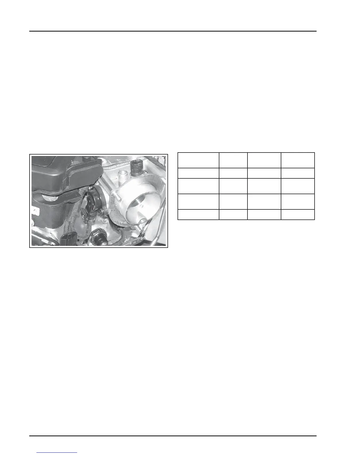
Mounted on the thro le body and operated directly
off the end of the thro le sha , the TPS works as a
potentiometer, varying the voltage signal to the ECU
in direct correlation to the angle of the thro le plate.
This signal, along with the other sensor signals, is
processed by the ECU and compared to the internal
preprogrammed maps to determine the required fuel
and ignition se ings for the amount of load.
The correct position of the TPS is established and
set at the factory. Do not loosen the TPS or alter the
mounting position unless absolutely required by fault
code diagnosis. If the TPS is loosened or repositioned,
the appropriate TPS Learn Procedure must be
performed to re-establish the baseline relationship
between the ECU and the TPS.
Figure 5-5. TPS Location.
Service
The TPS is a sealed, non-serviceable assembly.
If diagnosis indicates a bad sensor, complete
replacement is necessary. If a blink code indicates a
problem with the TPS, it can be tested as follows:
1. Counting the number of turns, back out the idle
speed adjusting screw (counterclockwise) until
the thro le plates can be closed completely. Write
this number down for reference later.
2. Disconnect the Black connector from the ECU,
but leave the TPS mounted to the thro le body.
3. a. Use an ohmmeter and connect the red
(positive) ohmmeter lead to Black pin 12
terminal and the black (negative) ohmmeter
lead to Black pin 10 terminal to test.
b. Hold the thro le closed and check the
resistance. It should be 1400-1800 Ω.