5.13
Section 5
EFI Fuel System
5
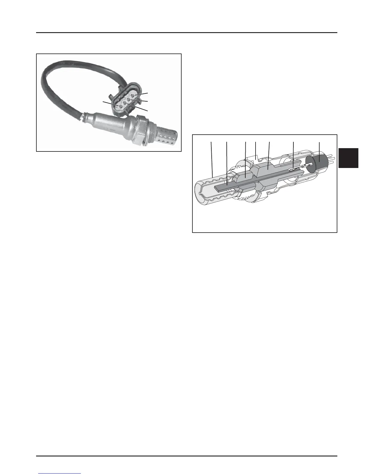
Figure 5-9. Oxygen Sensor.
General
The oxygen sensor functions like a small ba ery,
generating a voltage signal to the ECU based upon the
diff erence in oxygen content between the exhaust gas
and the ambient air.
The tip of the sensor, protruding into the exhaust gas,
is hollow (see cutaway Figure 5-10). The outer portion
of the tip is surrounded by the exhaust gas, with the
inner portion exposed to the ambient air. When the
oxygen concentration on one side of the tip is diff erent
than that of the other side, a voltage signal up to 1.0
volt is generated and sent to the ECU. The voltage
signal tells the ECU if the engine is straying from
the ideal fuel mixture, and the ECU then adjusts the
injector pulse accordingly.
The oxygen sensor functions a er being heated to a
minimum of 400°C (752°F). A heater inside the sensor
heats the electrode to the optimum temperature in
about 10 seconds. The oxygen sensor receives the
ground through the wire, eliminating the need for
proper grounding through the muffl er. If problems
indicate a bad oxygen sensor, check all connections
and wire harness. The oxygen sensor can also be
contaminated by leaded fuel, certain RTV and/or other
silicone compounds, fuel injector cleaners, etc. Use
only those products indicated as O
2
Sensor Safe.
12 345 6
7
1. Protection Shield
2. Planar Element and Heater
3. Lower Insulator
4. Stainless Steel Housing
5. Upper Insulator
6. Terminal Connection to
Element
7. High Temp Water Seal
Pin D
Pin C
Pin B
Pin A
Oxygen Sensor
Service
The temperature must be controlled very accurately
and gas constituents measured to a high degree of
accuracy for absolute sensor measurements. Since
this requires laboratory equipment, it is not possible
to distinguish a marginally in specifi cation sensor
from a marginally out of specifi cation sensor with
simple fi eld diagnostic equipment. Furthermore, as
with most devices, intermi ent problems are diffi cult
to diagnose. Still, with a good understanding of the
system and the sensor, it is possible to diagnose many
sensor problems in the fi eld.
Figure 5-10. Cutaway of Oxygen Sensor.
Using diagnostic so ware connected to the ECU is a
useful technique for observing sensor performance.
However, the user must understand that such
so ware reads a signal generated by the ECU. If there
is an ECU or wiring problem, the readings could
be misinterpreted as a sensor problem. The digital
nature of the signal to the so ware means that it
is not reading the continuous output of the sensor.
A voltmeter can also be used as an eff ective tool in
diagnosing sensors. It is advisable to use an electronic
meter such as a digital voltmeter. Simple mechanical
meters may place a heavy electrical load on the sensor
and cause inaccurate readings. Since the resistance of
the sensor is highest at low temperatures, such meters
will cause the largest inaccuracies when the sensor is
in a cool exhaust.