5.12
Section 5
EFI Fuel System
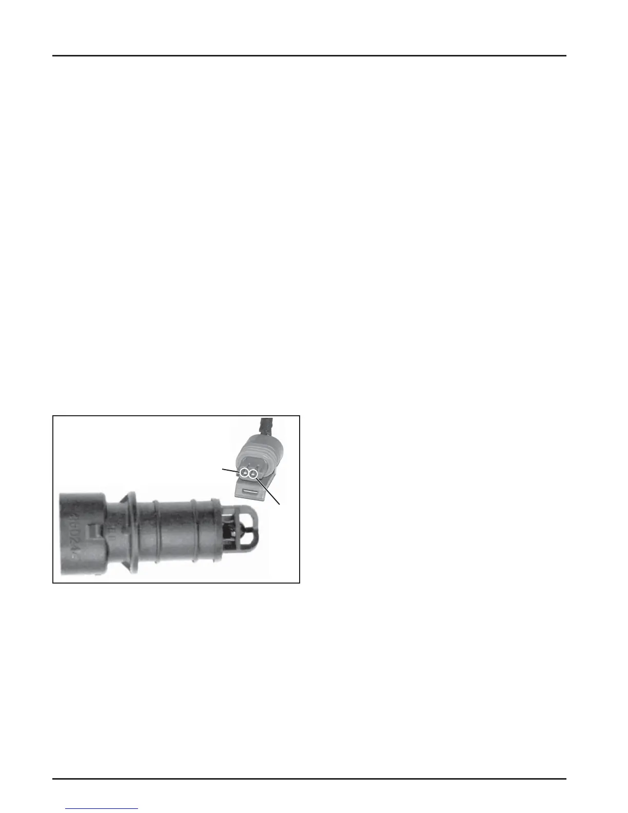
Figure 5-8. Intake Air Temperature Sensor.
General
The Intake Air Temperature (IAT) sensor is a
thermally sensitive resistor that exhibits a change in
electrical resistance with a change in its temperature.
When the sensor is cold, the resistance of the sensor
is high, and the voltage signal is high. As the sensor
warms up, the resistance drops and voltage signal
decreases. From the voltage signal, the ECU can
determine the temperature of the intake air.
The purpose of an air temperature sensor is to help
the ECU calculate air density. The higher the air
temperature gets the less dense the air becomes. As
the air becomes less dense the ECU knows that it
needs to lessen the fuel fl ow to achieve the correct
air/fuel ratio. If the fuel ratio was not changed the
engine would become rich, possibly losing power and
consuming more fuel.
Service
The intake air temperature sensor is a non-serviceable
component. Complete replacement is required if it is
faulty. The sensor and wiring harness can be checked
as follows.
1. Remove the temperature sensor from the thro le
body.
2. Allow it to reach room temperature (20°C, 68°F).
3. Unplug the Black connector from the ECU.
4. With the sensor still connected, check the
temperature sensor circuit resistance between the
Black pin 10 and 8 pin terminals. The value
should be 3100-3900 .
5. Unplug the sensor from the wire harness and
check the sensor resistance separately across the
two pins. Resistance value should again be
3100-3900 .
a. If the resistance is out of specifi cations, replace
the temperature sensor.
b. If it is within specifi cations, proceed to Step 6.
6. Check the circuits (input, ground), from the main
harness connector to the sensor plug for
continuity, damage, etc. Connect one ohmmeter
lead to Black pin 8 in the main harness connector
(as in step 4). Connect the other lead to terminal
#1 in the sensor plug (see Figure 5-8). Continuity
should be indicated. Repeat the test between
Black pin 10 and terminal #2 in the sensor plug.
3. Unplug the Black connector from the ECU.
4. With the sensor still connected, check the
temperature sensor circuit resistance between the
Black pin 10 and 14 terminals. The value should
be 9000-11000 .
5. Unplug the sensor from the wire harness and
check the sensor resistance separately across the
two pins. Resistance value should again be
9000-11000 .
a. If the resistance is out of specifi cations,
replace the temperature sensor.
b. If it is within specifi cations, proceed to Step 6.
6. Check the circuits (input, ground), from the wire
harness connector to the sensor plug for
continuity, damage, etc. Connect one ohmmeter
lead to Black pin 14 in the wire harness connector
(as in step 4). Connect the other lead to terminal
#1 in the sensor plug (see Figure 5-7). Continuity
should be indicated. Repeat the test between
Black pin 10 and terminal #2 in the sensor plug.
Intake Air Temperature Sensor
Pin 1
Pin 2