9.4
Section 9
Inspection and Reconditioning
Figure 9-6. Valve Details.
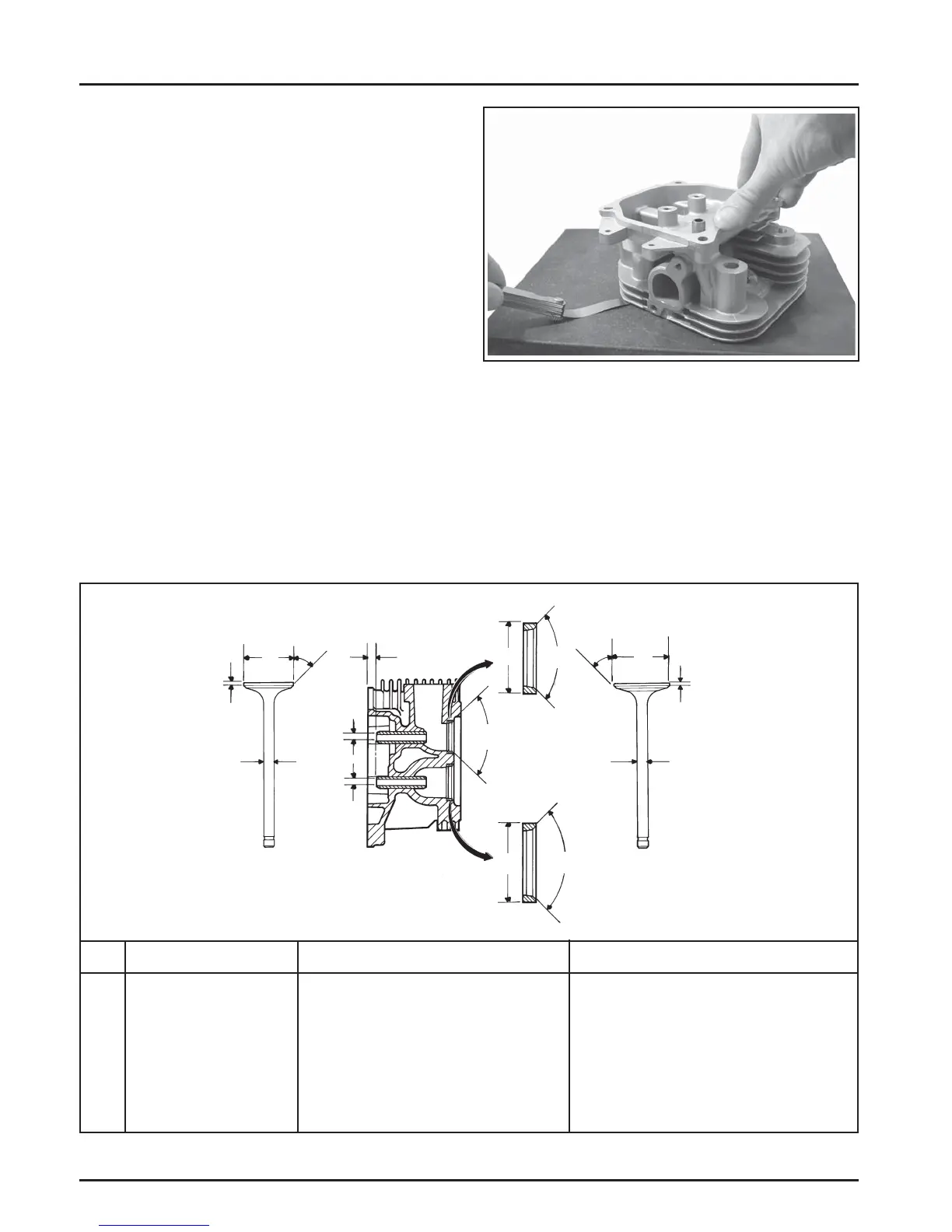
Figure 9-5. Checking Cylinder Head Flatness.
Carefully inspect the valve mechanism parts. Inspect
the valve springs and related hardware for excessive
wear or distortion. Check the valves and valve seat
area or inserts for evidence of deep pi ing, cracks,
or distortion. Check clearance of the valve stems
in the guides. See Figure 9-6 for valve details and
specifi cations.
Flywheel
Inspection
Inspect the fl ywheel for cracks, and the fl ywheel
keyway for damage. Replace fl ywheel if it is cracked.
Replace the fl ywheel, the cranksha , and the key if the
fl ywheel key is sheared or the keyway is damaged.
Inspect the ring gear for cracks or damage. Kohler
does not provide ring gears as a serviceable part.
Replace the fl ywheel if the ring gear is damaged.
Cylinder Head and Valves
Inspection and Service
A er cleaning, check the fl atness of the cylinder head
and the corresponding top surface of the crankcase,
using a surface plate or piece of glass and feeler gauge
as shown in Figure 9-5. The maximum allowable out
of fl atness is 0.076 mm (0.003 in.).
EXHAUST
VALVE
E
G
F
H
D
D
C
A
B
A
B
A
F
E
G
H
INTAKE VALVE
EXHAUST
INSERT
INTAKE
INSERT
A
B
C
D
E
F
G
H
Seat Angle
Insert O.D.
Guide Depth
Guide I.D.
Valve Head Diameter
Valve Face Angle
Valve Margin (Min.)
Valve Stem Diameter
Dimension
89°
36.987/37.013 mm (1.4562/1.4572 in.)
4 mm (0.1575 in.)
7.040/7.060 mm (0.2772/0.2780 in.)
33.37/33.63 mm (1.3138/1.3240 in.)
45°
1.5 mm (0.0591 in.)
6.982/7.000 mm (0.2749/0.2756 in.)
Intake
Exhaust
89°
32.987/33.013 mm (1.2987/1.2997 in.)
4 mm (0.1575 in.)
7.040/7.060 mm (0.2772/0.2780 in.)
29.37/29.63 mm (1.1563/1.1665 in.)
45°
1.5 mm (0.0591 in.)
6.970/6.988 mm (0.2744/0.2751 in.)