8.13
Section 8
Disassembly
8
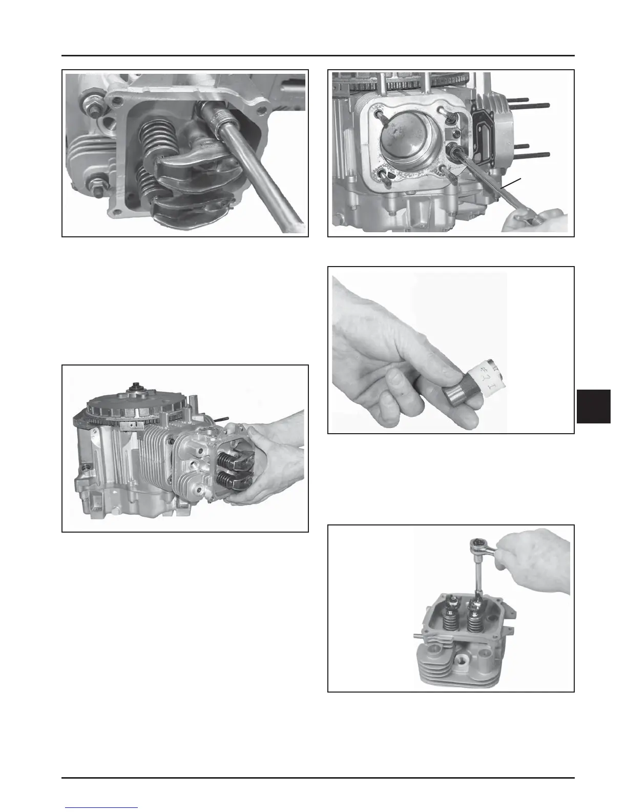
Figure 8-50. Removing Cylinder Head Fasteners.
2. Mark the location of the push rods as either
intake or exhaust and cylinder 1 or 2. Push
rods should always be reinstalled in the same
positions.
3. Carefully remove the push rods, cylinder heads,
and head gaskets. See Figure 8-51.
Figure 8-51. Removing Cylinder Head.
4. Remove the li ers from the li er bores. Use a
hydraulic li er tool. Do not use a magnet to
remove li ers. Mark the li ers by location, as
either intake or exhaust, and cylinder 1 or 2.
Hydraulic li ers should always be reinstalled in
the same position. See Figure 8-52 and 8-53.
Hydraulic
Lifter Tool
Figure 8-52. Removing Hydraulic Lifters.
Figure 8-54. Removing Rocker Arm.
2. Compress the valve springs using a valve spring
compressor. See Figure 8-55.
Figure 8-53. Mark the Lifters By Location.
Disassemble Cylinder Heads
1. Remove the two hex fl ange screws, rocker arm
pivots and rocker arms from the cylinder head.
See Figure 8-54.
 Loading...


