8.15
Section 8
Disassembly
8
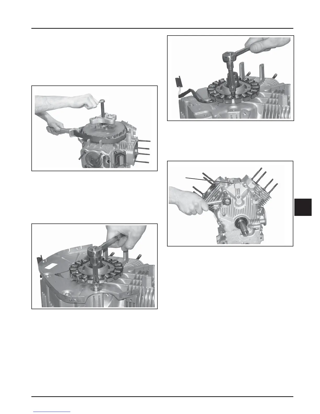
Figure 8-59. Removing Flywheel with a Puller.
5. Remove the woodruff key.
Remove Stator and Backing Plates
1. Remove the four screws securing the backing
plate. See Figure 8-60. Remove the backing plate.
NOTE: Always use a fl ywheel puller to remove
the fl ywheel from the cranksha . Do
not strike the cranksha or fl ywheel,
as these parts could become cracked
or damaged. Striking the puller or
cranksha can cause the crank gear to
move, aff ecting cranksha endplay.
Figure 8-61. Removing Stator.
Remove Oil Pan Assembly
1. Remove the ten hex fl ange screws securing the oil
pan to the crankcase. See Figure 8-62.
Figure 8-62. Removing Oil Pan Fasteners.
2. Locate the spli ing tab cast into the perimeter
of the oil pan. Insert the drive end of a 1/2 in.
breaker bar between the spli ing tab and the
crankcase and turn it to loosen seal. See Figure
8-62. Do not pry on the sealing surfaces as this
can cause leaks. Tap with a rubber mallet to fi nish
removing the oil pan. Remove the oil seal and
replace at reassembly.
Governor Gear Assembly
The governor gear assembly is located inside the
oil pan. If service is required, refer to the service
procedures under Governor Gear Assembly in
Section 9.
Oil Pump Assembly
The oil pump is mounted inside the oil pan. If service
is required, refer to the service procedures under Oil
Pump Assembly in Section 9.
Figure 8-60. Removing Backing Plate.
2. Remove the two hex fl ange screws and the stator.
See Figure 8-61. Note the position/routing of the
stator lead.
Splitting
Tab
 Loading...


