10.7
Section 10
Reassembly
10
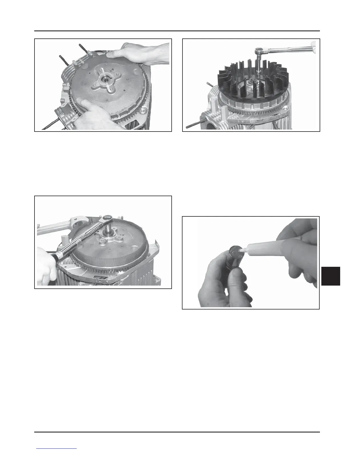
Figure 10-21. Carefully Align Keyway to Key.
3. Install the hex fl ange screw and washer.
4. Use a fl ywheel strap wrench or holding tool to
hold the fl ywheel. Torque the hex fl ange screw
securing the fl ywheel to the cranksha to
71.6 N·m (52.8 . lb.). See Figure 10-22.
Figure 10-22. Installing and Torquing Flywheel
Fastener.
Install Fan
1. Install the fan onto the fl ywheel using the four
hex fl ange screws (engines with plastic grass
screen). For engines with a metal grass screen,
leave it loosely assembled.
NOTE: Position the locating tabs on the back of the
fan into the locating holes of the fl ywheel. See
Figure 10-23.
2. Torque the screws to 9.9 N·m (88 in. lb.).
Figure 10-23. Installing Fan.
Install Cylinder Heads and Hydraulic
Lifters
1. See Servicing Hydraulic Li ers in Section 9 for
li er preparation (bleed down) procedures.
2. Apply camsha lubricant (see Section 2) to the
bo om surface of each li er. See Figure 10-24.
Lubricate the hydraulic li ers and the li er bores
in the crankcase with engine oil.
Figure 10-24. Applying Camshaft Lubricant to
Bottom of Lifters.
3. Note the mark or tag identifying the hydraulic
li ers as either intake or exhaust and cylinder 1
or cylinder 2. Install the hydraulic li ers into
their appropriate locations in the crankcase. Do
not use a magnet. See Figure 10-25.
 Loading...


