6.4
Section 6
Lubrication System
Oil Sentry
™
General
Some engines are equipped with an optional Oil
Sentry™ switch. This switch is designed to prevent
the engine from being started in a low oil or no oil
condition. The Oil Sentry™ may not shut down
a running engine before damage occurs. In some
applications this switch may activate a warning signal.
Read your equipment manual for more information.
The pressure switch is designed to make contact as the
oil pressure decreases below 2-5 psi depending upon
the application and switch specifi ed.
On stationary or una ended applications (pumps,
generators, etc.), the pressure switch can be used to
ground the ignition module to stop the engine. On
vehicular applications (lawn tractors, mowers, etc.)
the pressure switch can only be used to activate a low
oil warning light or signal.
NOTE: Make sure the oil level is checked BEFORE
EACH USE and is maintained up to the F
mark on the dipstick. This includes engines
equipped with Oil Sentry™.
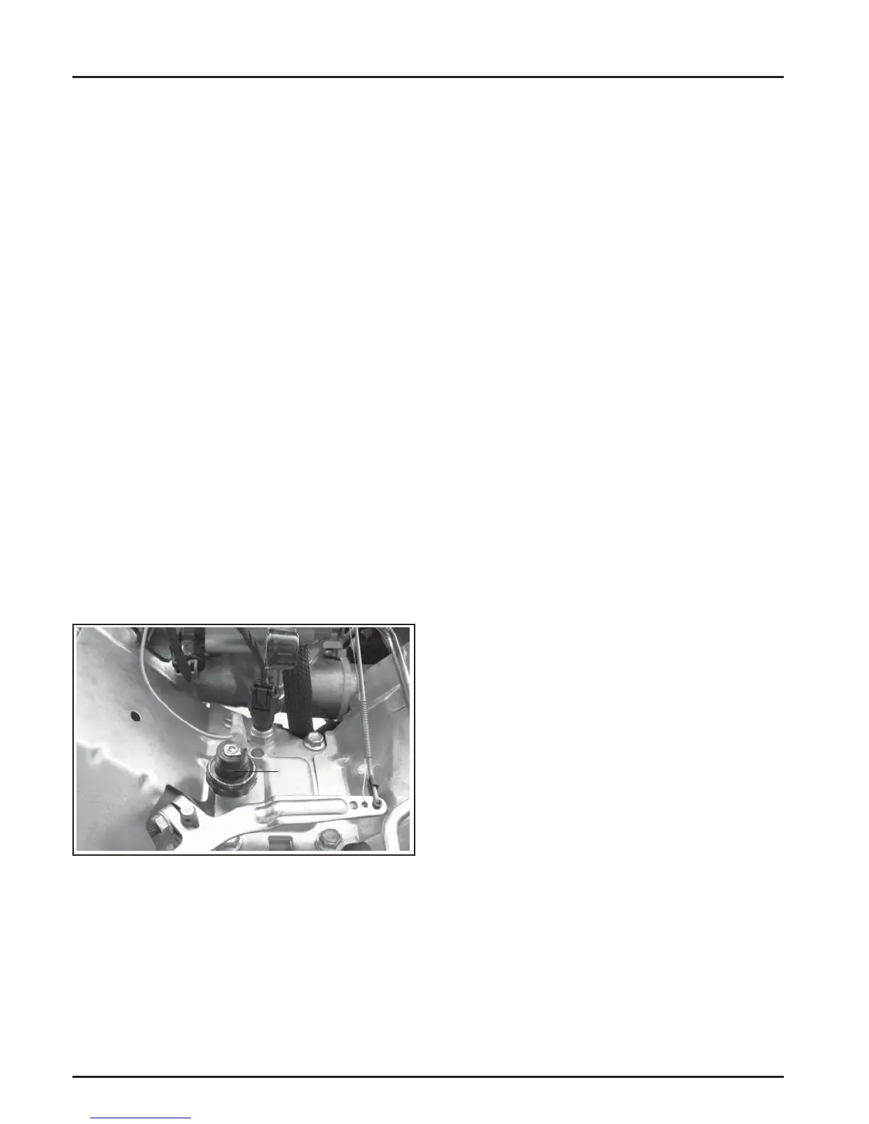
Installation
The Oil Sentry™ pressure switch is installed into the
breather cover. See Figure 6-8.
To install the switch, follow these steps:
1. If no sealant is preapplied, apply pipe sealant
with Tefl on
®
(Loctite
®
592
™
PST
®
Thread Sealant
or equivalent) to the threads of the switch.
2. Install the switch into the tapped hole in the
breather cover. See Figure 6-8.
3. Torque the switch to 4.5 N·m (40 in. lb.).
4. A ach lead to switch terminal.
Testing the Switch
Compressed air, a pressure regulator, pressure gauge
and a continuity tester are required to test the switch.
Normally Closed Switch
1. Connect the continuity tester across the blade
terminal and the metal case of the switch. With
0 psi pressure applied to the switch, the tester
should indicate continuity (switch closed).
2. Gradually increase the pressure to the switch.
As pressure increases through the range of
2.0/5.0 psi, the tester should indicate a change to
no continuity (switch open). The switch should
remain open as the pressure is increased to
90 psi maximum.
3. Gradually decrease the pressure through the
range of 2.0/5.0 psi. The tester should indicate a
change to continuity (switch closed) down to
0 psi.
4. Replace the switch if it does not operate as
specifi ed.
Normally Open Switch
1. Connect the continuity tester across the blade
terminal and the metal case of the switch. With
0 psi pressure applied to the switch, the tester
should indicate no continuity (switch open).
2. Gradually increase the pressure to the switch.
As pressure increases through the range of
2.0/5.0 psi, the tester should indicate a change to
continuity (switch closed). The switch should
remain closed as the pressure is increased to
90 psi maximum.
3. Gradually decrease the pressure through the
range of 2.0/5.0 psi. The tester should indicate a
change to no continuity (switch open) down to
0 psi.
Figure 6-8. Location of Oil Sentry™ Switch.
On engines not equipped with Oil Sentry
™
the
installation hole is sealed with a 1/8-27 N.P.T.F. pipe
plug.
Oil
Sentry™
 Loading...


