55Section 3 Decision-Makerr 3+ TroubleshootingTP-6356 4/12
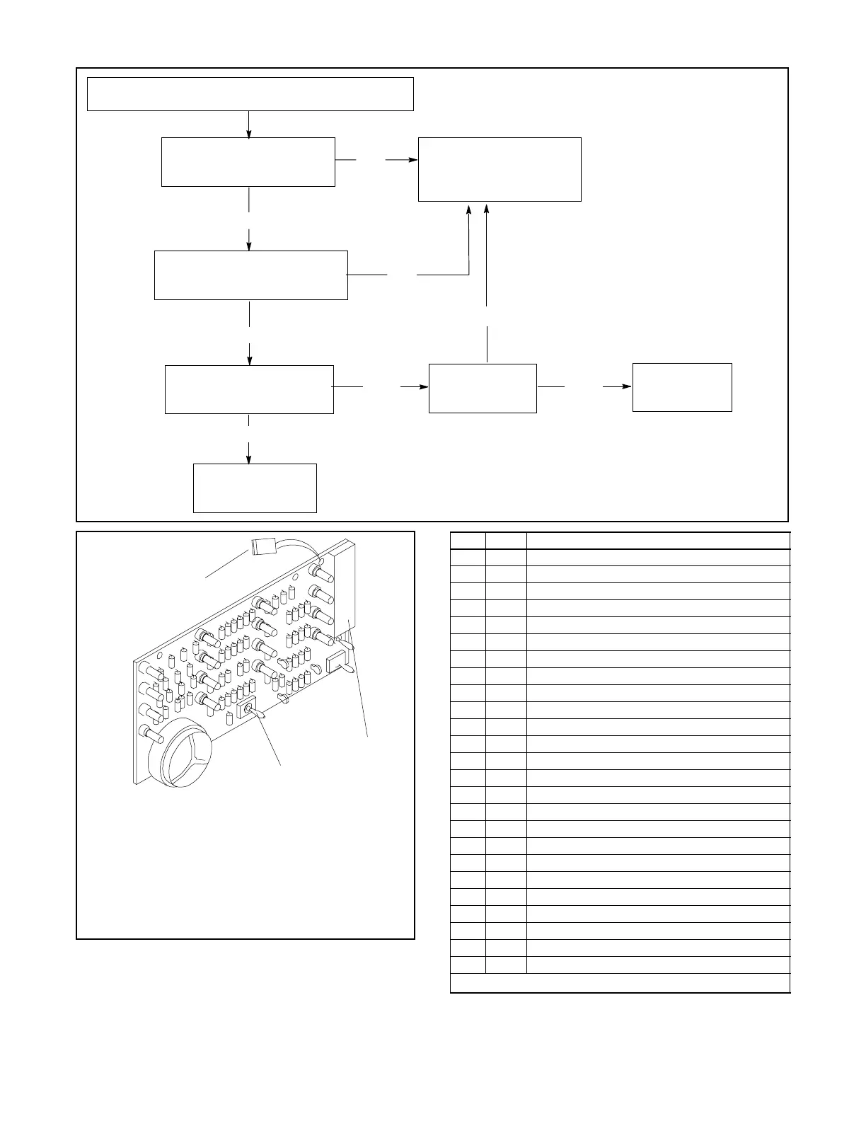
Generator Set Master Switch on Indicator Panel Circuit Board
Does the Not In Auto lamp
light when the master switch
is in OFF/RESET position?
Indicator panel circuit board not functioning or not
functioning properly (generator set master switch only).
Troubleshooting indicator
panel circuit board and
wiring. See Figure 3-22
and Figure 3-23.
Does the System Ready lamp
light when the switch is in the
AUTO position?
Indicator panel
circuit board switch
checks out okay.
Does the unit start when
the switch is in the RUN
position?
Does engine
start system
check out okay?
No
Yes
Yes
No
No
No
Troubleshoot
engine start
system.
Yes
Yes
A-336432
1. T27 Lead
2. P4 Connector. Check lamp (LEDs) using a 12-volt battery
connected to P4-6 (12 VDC+) and P4-1 (ground). Individual
LEDs should illuminate when each corresponding P4 pin is
grounded.
3. Generator Set Master Switch SW3. Check switch continuity
with an ohmmeter between P4-1/P4-23 (OFF/RESET),
P4-1/P4-24 (RUN), and P4-1/P4-4 (AUTO).
Note: Test for continuity in both directions by reversing test
probes as the circuit contains diodes.
1
3
2
Figure 3-22 Indicator Panel Circuit Board
P4- Wire Description
1 2 Ground
2 — —
3 — —
4 46 Auto
5 — —
6 24 12 VDC
7 38 Low Oil Pressure *
8 39 Overspeed *
9 12 Overcrank *
10 26 Auxiliary *
11 48 Emergency Stop *
12 40 Anticipatory High Engine Temperature *
13 36 High Engine Temperature *
14 60 System Ready *
15 80 NotinAuto*
16 35A Low Water Temperature *
17 41 Anticipatory Low Oil Pressure *
18 56 Air Damper *
19 62 Low Battery Voltage *
20 61 Battery Charger Fault *
21 63 Low Fuel *
22 32 Common Fault
23 43 Off/Reset
24 47 Run
T27 — High Battery Voltage
* Ground P4 pin to test
Figure 3-23 Indicator Panel Circuit Board P4
Connections