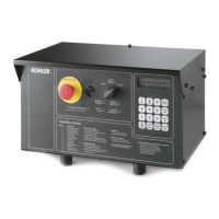
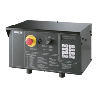
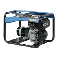
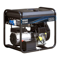
Do you have a question about the Kohler Decision-Maker 6000 and is the answer not in the manual?
Features, specifications, and settings for the Decision-Maker 550 controller's integrated voltage regulator.
Features, specifications, and settings for the Decision-Maker 3000 controller's integral voltage regulator.
Features, specifications, and settings for the Decision-Maker 6000 controller's integral voltage regulator.
Guidance on using charts for troubleshooting problems and understanding relay functions.
A troubleshooting flowchart to diagnose issues with the Decision-Maker 1 relay controller.
Details on controller circuit board service kits, including introduction, required items, and procedure.
Explanation of display messages, including requests, status, and error messages encountered during operation.
Procedure for replacing a non-functional controller using service replacement kits.
Instructions for replacing coolant temperature sensors and performing software upgrades.
Procedure for installing a replacement controller, including acquiring user parameters and installation steps.
Explanation of display messages indicating requests, status, and errors during controller operation.
Procedure for installing a replacement controller, including acquiring user parameters and replacement steps.
Guidelines for safely handling electronic printed circuit boards (PCBs) during removal, installation, and storage.
Function, application, and adjustment procedures for the reactive droop compensator used in parallel generator operation.
Safety instructions regarding the risk of severe injury or death from accidental generator set starting.
Safety warnings related to sulfuric acid in batteries, explosion risks, and handling battery acid.
Safety precautions concerning fire hazards from fuels, fuel vapors, and servicing the fuel system.
Safety warnings about explosive fuel vapors and precautions when handling, storing, and using fuels.
Warnings about severe injury or death from hazardous voltage, moving parts, and electrical backfeed.
Description of natural gas and LPG fuel systems not covered in standard engine manuals.
Information on converting between natural gas and LPG fuels, including potential output changes and ECM programming.
Explanation of gas fuel systems utilizing fuel valves, regulators, and mixers for varying conditions.
Procedures for converting between LP gas and natural gas fuels, including regulator adjustments and specs.
Instructions for converting GM-powered generator sets from natural gas to LP gas vapor.
Procedure for adjusting fuel mixture using an oxygen sensor and digital voltmeter for CARB/EPA non-certified sets.
Instructions for converting GM-powered generator sets from natural gas to LP gas vapor, including mixer and regulator replacement.
Procedure for adjusting fuel mixture using an oxygen sensor and digital voltmeter for GM-powered sets.
Introduction to the programming kit, kit components, features, PC requirements, and user interface overview.
Instructions for basic governor adjustments and calibration techniques for optimum engine performance.
Troubleshooting charts to diagnose generator set/engine problems related to the governor controller.
| Brand | Kohler |
|---|---|
| Model | Decision-Maker 6000 |
| Category | Portable Generator |
| Language | English |


