TP-6356 4/1232 Section 2 Decision-Makerr 1 Troubleshooting
2.2 Relay Controller
Use the following charts as a reference in
troubleshooting individual problems. Before beginning
any troubleshooting procedure, read all safety
precautions at the beginning of this manual and those
included in the text. Do not neglect these precautions.
Accidental starting.
Can cause severe injury or death.
Disconnect the battery cables before
working on the generator set.
Remove the negative (--) lead first
when disconnecting the battery.
Reconnect the negative (--) lead last
when reconnecting the battery.
WARNING
Disabling the generator set. Accidental starting can
cause severe injury or death. Before working on the
generator set or connected equipment, disable the generator
set as follows: (1) Move the generator set master switch to the
OFF position. (2) Disconnect the power to the battery charger.
(3) Remove the battery cables, negative (--) lead first.
Reconnect the negative (--) lead last when reconnecting the
battery. Follow these precautions to prevent starting of the
generator set by an automatic transfer switch, remote
start/stop switch, or engine start command from a remote
computer.
Hazardous voltage.
Can cause severe injury or death.
Operate the generator set only when
all guards and electrical enclosures
areinplace.
Moving parts.
WARNING
Grounding electrical equipment. Hazardous voltage can
cause severe injury or death. Electrocution is possible
whenever electricity is present. Ensure you comply with all
applicable codes and standards. Electrically ground the
generator set, transfer switch, and related equipment and
electrical circuits. Turn off the main circuit breakers of all
power sources before servicing the equipment. Never contact
electrical leads or appliances when standing in water or on wet
ground because these conditions increase the risk of
electrocution.
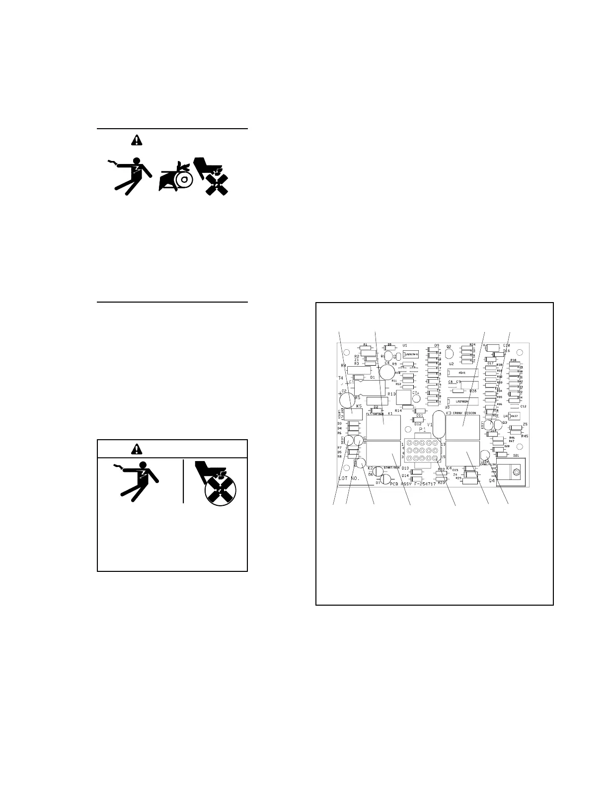
See Figure 2-6 and use the flowchart in Section 2.3 to
assist in troubleshooting the main circuit board and the
generator set. If the prescribed remedy does not correct
the problem, replace the circuit board. The controller
circuit board includes light emitting diodes (LEDs)
indicating relay coil power and aids in circuit board and
generator set fault detection. When the K1, K2, K3, K4,
or K5 relays receive power, the corresponding LED
lights. The LED does not indicate whether the relay coil
is energized. Determine if relay coil is energized by
analyzing the generator set faults and performing a
continuity test on the relay coil.
F-254717-A
12 34
56789
1011
1. K5 relay (fault latch)
2. K1 relay (fault)
3. K3 relay (crank/disconnect)
4. LED3
5. LED4
6. K4 relay (crank/flash)
7. P1 connector
8. K2 relay (start/run)
9. LED2
10. LED1
11. LED5
Figure 2-6 Controller Circuit Board F-254717