36 Section 1 Specifications TP-6953 7/19
1.17.1 Specificat ions and Features
Specification/Feature
Voltage Regulator Type Integral with Decision-Makerr 3500
Integrated Voltage Regulator Patented Hybrid Design
Status and Shutdown Indicators LEDs and Graphical LCD Display
Operating Temperature
-40_Cto70_C(-40_Fto158_F)
Storage Temperature
-40_Cto85_C(-40_ Fto185_F)
Humidity Withstand 5- 95% Condensing
Salt Spray Tolerance 5% Salt Spray per ASTM-B-117-90
Circuit Protection Solid-State, Redundant Software and Fuses
Sensing, Nominal 100- 600 V (L-L), 50- 60 Hz
Sensing Mode RMS, Single- or 3-Phase
Input Requirements 8- 36 VDC
Continuous Output 5 VDC @ 100 mA max. 5.0 A DC with GM88453 Activator Board
Maximum Forcing Output 5 VDC @100 mA max. 7.8 ADC with GM88453 Activator Board
Transition Frequency 42.0- 62.0 Hz
Exciter Field Resistance 4 - 30 Ohms with GM88453 Activator Board
No-Load to Full-Load Voltage Regulation 0.5%
Thermal Drift
<0.5% (- 40_Cto70_C) [- 40_F to 158_F ] Range
Response Time Less than 5mS
System Voltage Adjust Range 10%
Voltage Adjustment Controller Menu Knob
Remote Voltage Adjustment 0.5- 4.5 VDC (10%) Bias Input
Paralleling Capability Reactive Droop plus Load Share and Control
VAR/PF Control Input VAR Control Mode, PF Control Mode, System VAR Control, System PF Control
1.17.2 Integral Voltage Regulator
Adjustment Digital Display Range Setting Default Selection
Voltage Adjustment Voltage Adjust 10% of System Voltage System Voltage
V/Hz Cut-in V/Hz Setpoint 42 to 62 Hz 1.0 Hz Below Nominal Frequency
Underfrequency Unload Slope V/Hz Slope 0- 10% of System Voltage (Volts per Cycle) 5% of Rated Voltage per Cycle
Reactive Droop
Volt Droop @
100% kVAR
0.0% to 20% of System Voltage 1% of System Voltage
Voltage Regulator Gain Adjust Voltage Gain Adjust 1to255 128
Startup Voltage Ramp Rate Startup Ramp Rate 5.0% to 100.0%/Sec 25%/Sec
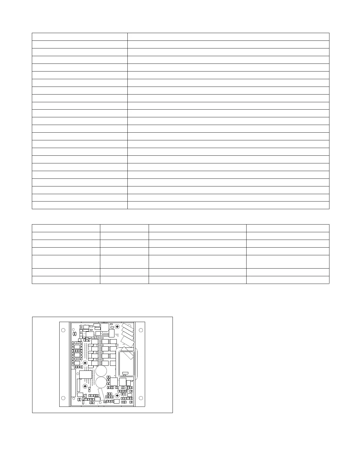
1.17.3 Activator Board GM88453
(13- 32EKOZD/11- 28EFKOZD
Models)
D Interfaces between the controller and alternator assembly
using rotor field leads, auxiliary power windings, and
optic board leads.
D Allows the Decision-Makerr controller the ability to
control a wound-field alternator using the same control
signal as the Fast Responset alternator.
D Permits the generator set controller to control the current
to the exciter field of a wound-field excited alternator.
D Contains two isolated relay driver outputs (RDO) rated at
250 mA. Provides RDO outputs indicating a field over-
excitation condition and that the alternator is supplying
voltage to the activator.
 Loading...