Do you have a question about the Kohler 15EKOZD and is the answer not in the manual?
Procedure and warnings for preventing accidental generator startup to avoid injury or death.
Warnings and precautions related to risks of fire and explosion from engine backfire.
Safety warnings regarding carbon monoxide hazards from the exhaust system.
Safety warnings and precautions for handling fuels and fuel vapors to prevent fires.
Safety warnings regarding electrical hazards and dangers from moving parts.
Information on how to obtain professional advice and service for generator sets.
Overview of the manual's scope and guidance on consulting generator set nameplates.
Detailed specifications for the engine used in the generator sets.
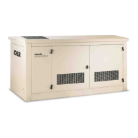
Illustrations and labels identifying key components and service points on the generator set.
A comprehensive list of checks to perform before starting the generator set.
Recommendations for maintaining minimum load to prevent engine wet stacking.
Explanation of the Decision-Maker® 3500 controller modes and functions.
Guidelines for scheduling routine maintenance based on operating hours and conditions.
Procedure for cleaning the alternator windings and cooling system.
Instructions for performing engine service at specified intervals.
Procedure for inspecting the exhaust system for leaks, blockages, and corrosion.
Procedure for checking and cleaning the mixing elbow for carbon buildup.
Overview of the fuel system and considerations for installations.
Information on fuel filter replacement and its impact on system life.
Procedure to remove air from the fuel system to prevent starting issues.
Description of the heat exchanger cooling system components.
Procedure for replacing coolant and servicing the heat exchanger.
Procedure for flushing and cleaning the cooling system.
Overview of troubleshooting procedures, diagnostics, and repair information.
Common problems to check first before replacing parts.
Charts to diagnose and correct common problems with probable causes and recommendations.
General guidelines for controller repair and service part replacement.
Necessary PC requirements and software for using SiteTecht.
Procedure for installing a replacement controller.
Guidelines for safely handling the controller and its components.
Information on repairing or replacing wiring and connectors.
Test procedure for crank relays, run relays, cold start, and flash relays.
Overview of troubleshooting and testing alternator components.
Procedure to separately excite the generator using an external voltage source.
Procedure for testing the exciter field resistance and for short-to-ground conditions.
Overview of troubleshooting and testing alternator components.
Flowcharts for troubleshooting alternator output conditions.
Procedure for testing the LED optic board.
Description of Decision-Maker® 3500 controller functions for various applications.
Requirements and considerations for external paralleling.
Requirements and considerations for internal paralleling.
Explains the purpose of Generator Management for optimizing generator operation.
Describes the basic functions of Generator Management for starting/stopping generators.
Parameters and considerations for configuring Generator Management.
Explains the purpose of Load Management for controlling loads.
Describes the basic functions of Load Management in Decision-Maker® 3500.
Step-by-step operation of Load Management in a single generator system.
Introduction to the alternator disassembly and reassembly procedures.
Step-by-step procedure for disassembling the alternator.
Step-by-step procedure for reassembling the alternator.
Disassembly procedures specific to 4PX/4QX alternators.
Reassembly procedures specific to 4PX/4QX alternators.
Reference guide to locate specific wiring diagrams for various models.
List of abbreviations used in the manual.
Guidelines for determining proper bolt and screw length.
Guidelines for selecting and using washers and nuts.
Torque specifications for American standard fasteners.
Torque specifications for metric fasteners.
Identification of common screw, bolt, and stud head styles.
Identification of common nut styles.
Identification of common washer styles.
List of common hardware items for American standard fasteners.
List of common hardware items for metric fasteners.
Practices to minimize signal coupling between circuits.
| Type | Portable Generator |
|---|---|
| Fuel Type | Gasoline |
| Run Time at 50% Load | 10 hours |
| Voltage | 120/240V |
| Frequency | 60 Hz |
| Starting System | Electric Start |
| Power Output | 15 kW |
| Rated Watts | 15000 watts |
| Phase | Single Phase |
| Dimensions (L x W x H) | 48 x 29 x 33 in |
| Warranty | 3 years limited warranty |