EasyManua.ls Logo

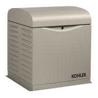
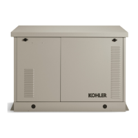
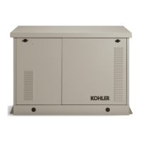
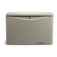
Kohler 12RESV

Kohler 12RESV
76 pages
To Next Page IconTo Next Page
Loading...
Residential/Commercial Generator Sets
Models:
8/10/12RESV
8/10/12RESVL
Controllers:
RDC2
DC2
TP-6880 10/14a
Operation

Table of Contents

Other manuals for Kohler 12RESV

Questions and Answers:

Kohler 12RESV Specifications

General IconGeneral
Voltage120/240 V
Frequency60 Hz
Power Output12 kW
PhaseSingle
EngineKohler
Fuel Tank CapacityN/A (Connects to Natural Gas or Propane Line)

Summary

Product Identification Information

Generator Set Identification Numbers

Record product identification numbers from the generator set nameplate.

Controller Identification

Record controller description from operation manual or spec sheet.

Engine Identification

Record product identification from the engine nameplate.

Introduction

List of Related Literature

Lists other manuals and documentation available for generator sets.

Nameplate

Emission Information

Details about engine emissions and compliance periods for different models.

Generator Set Application

Explains generator set usage limitations and compliance with the Clean Air Act.

Service Assistance

Section 1 Descriptions and Service Views

1.1 Introduction

Overview of manual content and where to find additional specifications.

1.2 Engine

Describes the four-cycle, air-cooled Kohler engines used in the generator sets.

1.3 Generator Set Enclosure

Details the steel enclosure, its protective finish, and access features.

1.4 Alternator

Explains the PowerBoostâ„¢ voltage regulation system and its benefits.

1.5 Transfer Switch

Discusses controller interface with the Model RXT Automatic Transfer Switch.

1.6 Controllers

Introduces the RDC2 and DC2 controllers and their integrated control functions.

1.7 OnCue Plus Generator Management System

Details the remote monitoring and control system for generator sets.

1.8 Accessories

Lists optional accessories available for the generator sets.

1.9 Service Views

Provides visual diagrams of generator set components and their locations.

Section 2 Generator Set Operation

2.1 Prestart Checklist

Essential checks to perform before starting the generator set.

2.2 Exercising the Generator Set

Explains the importance and procedure for weekly generator set exercise runs.

2.3 Generator Set Operation

Covers basic generator set start, stop, and automatic operation procedures.

2.4 Exercise

Details the procedures for setting and performing generator set exercise modes.

2.5 Faults

Explains fault messages, warnings, shutdowns, and controller reset procedures.

2.6 Generator Enclosure Thermostat

Information on the resettable thermostat and how to reset it.

Section 3 RDC2 Controller Operation

3.1 RDC2 Generator Set Transfer Switch Controller

Introduces the RDC2 controller and its functions.

3.2 Controls and Indicators

Details the RDC2 controller's keypad, LEDs, and LCD display.

3.3 Controller Power

Explains how the RDC2 controller receives power.

3.4 Battery Charging

Details the built-in battery charger for maintaining the starting battery.

3.5 Changing Settings

Provides the procedure for changing controller settings.

3.6 Setting the Exerciser

Explains how to set and change the generator set exercise schedule.

3.7 RDC2 Controller Menus

Overview of the controller's menu structure and navigation.

3.8 Main Menu

Describes how to access and navigate the main menu.

3.9 Overview Menu

Details the information displayed in the Overview menu.

3.10 Engine Metering Menu

Explains the engine status information available in the metering menu.

3.11 Generator Metering Menu

Details the generator voltage and frequency information.

3.12 Generator Set Information Menu

Displays model and serial numbers; no changes allowed.

3.13 Genset Run Time Menu

Shows engine runtime and next maintenance information.

3.14 Genset System Menu

Displays system information, including voltage, frequency, and settings.

3.15 ATS Status Menu

Displays Model RXT transfer switch and source information.

3.16 ATS Configuration Menu

Allows checking and changing ATS system settings and time delays.

3.17 Date and Time Menu

Procedure for setting the date, time, and time format.

3.18 Networking Information Menus

Information and settings for network and RBUS communication.

3.19 Programmable Interface Module (PIM) Status Menu

Displays the status of inputs and outputs for a connected PIM.

3.20 Load Control Module (LCM) or Load Shed Kit Menus

Shows status of LCM/Load Shed kit inputs/outputs and allows relay testing.

3.21 Event Log

Displays controller faults and notices with date, time, and description.

Section 4 DC2 Controller Operation

4.1 DC2 Generator Set Transfer Switch Controller

Introduces the DC2 controller and its controlled power system components.

4.2 Controls and Indicators

Details the DC2 controller's keypad, LEDs, and LCD display.

4.3 Controller Power

Explains how the DC2 controller receives power from the engine battery.

4.4 Battery Charging

Details the built-in battery charger for maintaining the engine starting battery.

4.5 Exercise

Covers exercise modes, setting the exerciser, and resetting it.

4.6 Event Log

Displays controller faults and notices, starting with the most recent event.

4.7 Maintenance Timer

Tracks time until the next recommended maintenance.

4.8 OnCue Plus Password

Procedure for setting the OnCue Plus password on the DC2 controller.

Section 5 Scheduled Maintenance

5.1 Scheduled Maintenance

Refers to schedules and runtime hours for planning routine maintenance.

5.2 Lubrication System

Information and procedures for oil checks and changes.

5.3 Spark Plugs

Instructions for checking, adjusting gap, and replacing spark plugs.

5.4 Air Cleaner Service

Procedures for servicing air cleaner elements for different models.

5.5 Cooling System

Importance of keeping cooling system openings clean and unobstructed.

5.6 Exhaust System

Guidelines for inspecting the exhaust system for leaks and obstructions.

5.7 Battery

Information on battery maintenance, cleaning, and connections.

5.8 Storage Procedure

Steps for preparing the generator set for storage.

Section 6 Troubleshooting

6.1 Introduction

Guide to using troubleshooting charts for diagnosing and correcting problems.

6.2 USB Port

Location and use of the USB port for connecting a computer for settings.

6.3 Fault Messages

Explains how fault messages aid in troubleshooting controller issues.

6.4 Circuit Protection

Discusses circuit breakers and internal controller protection.

6.5 Troubleshooting

A general chart for diagnosing and repairing common generator set problems.

Appendix A Abbreviations

Related product manuals