TP-5700 7/93 15Section 4 Air Requirements
4.5 Air Vent
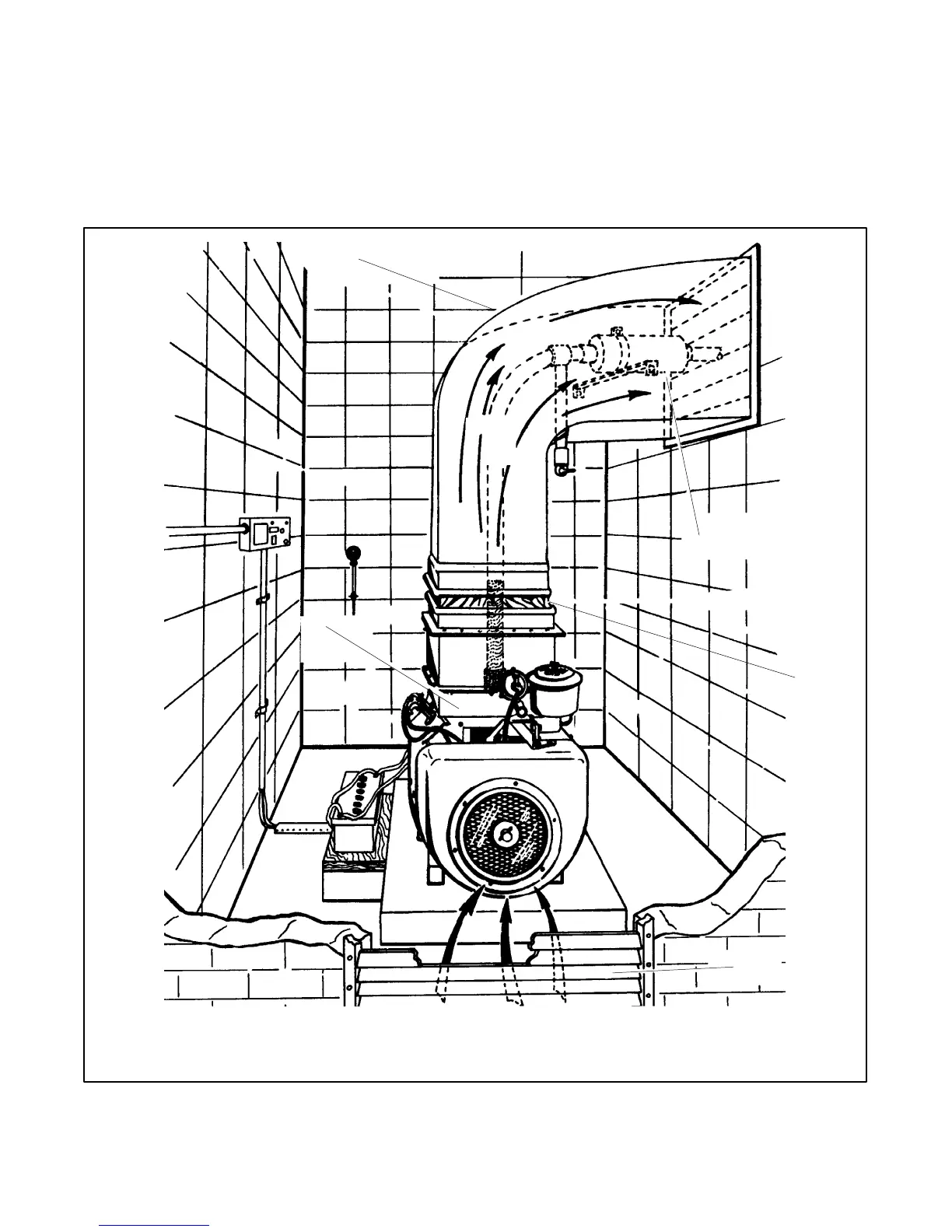
The air vent system is used on some air-cooled gas and
has been used on some diesel models. It includes
special ductwork which directs the flow of heated air to
the outlet at the top or side of the engine. The air vent air
flow is not reversed as it is with the Air-Vac system.
Choose top or side outlet of the engine. Additional
ductwork connects to the engine ductwork carrying the
heated air outside. For duct dimensions, refer to the
dimensional drawing for the particular unit. This system
is also efficient in maintaining consistent operating
temperatures in confined areas. See Figure 4-7.
Note: Air vent requires very little engine modification
making it practical for field installation.
TP-5700-4
1
2
3
4
5
6
1. Ductwork with gradual bend
2. Heated air out
3. Exhaust Muffler
4. Canvas section
5. Air inlet opening
6. Air vent adapter
Figure 4-7 Air Vent Cooling System using an Air-Cooled Generator Set
 Loading...
