TT-1379 5/16 9
Digital Gauge Modes:
Note: The digital gauge has three normal operating
modes: monitor, start/stop, and backlight adjust.
Use the SELECT button at the top of the gauge to
step through the modes.
Monitor Mode
Press the SELECT button until the display shows
generator set data and indicator arrows. Use the UP or
DOWN arrow to scroll through the data. The
corresponding illuminated arrow indicates which data is
being displayed. See Figure 17. Any faults are
displayed in blinking text. The following generator set
operation data is displayed in this mode:
D Voltage (AC volts)
D Oil pressure (psi or kPa). May require the
installation of an optional oil pressure
sender on the engine. See Figure 18.
D Engine speed (rpm)
D Frequency (Hz)
D Coolant temperature (_For_C)
D Runtime hours
D Battery voltage (VDC)
Note: The maximum battery voltage that the
ADC will display on the remote digital
gauge is 31.5 volts. If the voltage is
higher than 31.5, it will display 31.5 volts.
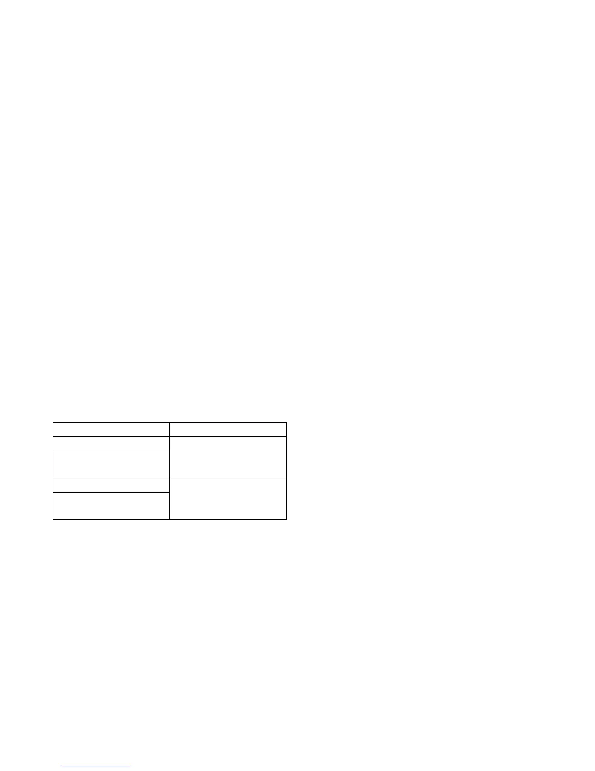
Model Oil Pressure Sender
EKD and EFKD
Optional
EOD and EFOD
EOZD and EFOZD
EGD, EFGD, and EGZD
StandardEKOD and EFKOD
EKOZD and EFKOZD
Figure 18 Models with Optional or Standard
Oil Pressure Sender
Start/Stop Command Mode
Press the SELECT button until the display shows SEND
RUN or SEND STOP. Use the UP or DOWN arrow to
send a remote start/stop command.
Note: The ADC 2100 must be powered (display active)
and the master switch must be in the AUTO
position for remote start/stop. If the ADC 2100
master switch is in the RUN position, a remote
stop command will not stop the generator set.
The arrow at the top left side of the display blinks
to indicate that the generator set is running (see
Figure 17, item 2).
Note: The ADC II and ADC IId must be powered
(display active) for remote start/stop.
Note: The Decision-Maker 3500 must be powered
(display active) and in the AUTO position for
remote start/stop. If in the RUN position, a
remote stop command will not stop the generator
set. The arrow at the top left side of the display
blinks to indicate that the generator set is running
(see Figure 17, item 2).
Refer to the generator set operation manual and follow
the safety precautions when operating the generator
set.
Backlighting Mode
Press the SELECT button until the display shows LEVL.
Use the UP or DOWN arrow to select a lighting level:
D 0 = no backlight
D 3 = brightest backlight.
Note: While in this mode, faults appear on the display,
however no audible alarm is heard.
Once set, the backlight level defaults to the last
selection.
The maximum power draw of the remote gauge is 50 mA
at 12 VDC (or 25 mA at 24 VDC) with the brightest
backlight.
To Silence an Audible Alarm:
Faults are indicated by blinking or solid text and an
audible alarm. To silence an audible a larm, press and
hold the UP and DOWN arrow buttons simultaneously
until the gauge emits a long beep and then release.
Note: For a fault warning, the background lamp is solid.
For a fault shutdown, the background lamp will
flash. Consult your operation manual for more
details on warnings and shutdowns.
 Loading...