TT-1379 5/16 3
Installation Procedure
1. Remove the generator set from service.
1.1 For generator sets with an ADC 2100
controller: Place the generator set master
switch in the OFF position.
For generator sets with an ADC II or ADC IId
controller: Press the start/stop button to stop
the generator set. Then, press the power button
to turn off the controller.
For generator sets with a Decision-Makerr
3500 controller: Press the OFF/RESET button
to shut down the generator set.
1.2 Disconnect the generator set engine starting
battery, negative (--) lead first.
2. Install the remote digital gauge.
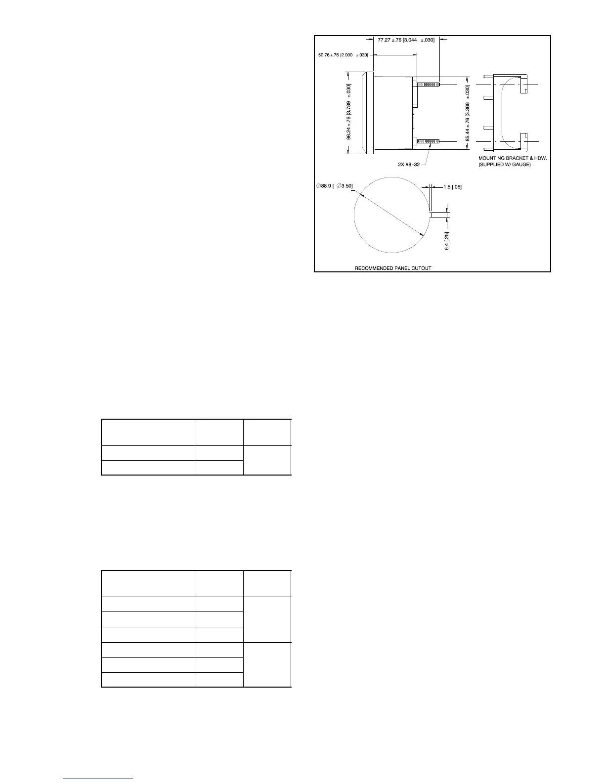
2.1 Select a dry location to mount the remote digital
gauge. Consider the length of the wiring
harness and the gauge’s mounting depth and
size when selecting a location. See Figure 5 for
the mounting dimensions.
2.2 For units with an ADC controller, order a remote
extension harness kit. See Figure 3 for kit
selection. Do not use more than 3 remote
harness kits and do not exceed 23 m (75 ft.) in
harness length.
Remote Extension
Harness Kit Number
Length
m (ft.)
As
Shown In
GM32333-KP1 4.6 (15)
Figure 8
GM32333-KP2 7.6 (25)
Figure 3 Remote Extension Harness Kits (For Units
with an ADC Controller)
For units with a Decision-Makerr 3500
controller, order a remote extension harness
kit. See Figure 4 for kit selection. DO NOT
exceed 91.4 m (300 ft.) CAN network length.
Remote Extension
Harness Kit Number*
Length
m (ft.)
As
Shown In
GM91774-KP1 7.6 (25)
Figure 11
GM91774-KP2 15.2 (50)
GM91774-KP3 30.5 (100)
GM92053-KP1 7.6 (25)
Figure 12GM92053-KP2 15.2 (50)
GM92053-KP3 30.5 (100)
* Y Harness shown in Figure 13
Figure 4 Remote Extension Harness Kits (For Units
with a Decision-Makerr 3500 Controller)
GM30565-B
NOTE: Dimensions in brackets
are inch equivalents.
Figure 5 Mounting Dimensions
2.3 Connect the 6-pin inline connector of the gauge
harness (GM32325 or GM100955) to the 6-pin
inline connector on the digital gauge. See
Figure 6 and Figure 7 or Figure 10.
2.4 For Kit GM32337-KP1: Connect the 12-pin
connector end of the gauge harness or a remote
extension harness to the generator set’s
customer-interface 12-pin connector. See
Figure 7, Figure 8, and Figure 9.
2.5 For Kit GM100956-KP1: Connect the 6-pin
connector end of the gauge harness to a remote
extension harness. See Figure 10, Figure 11,
Figure 12, Figure 13, Figure 14, and Figure 15.
Connect the lead ends of the e xtension harness
to the TB12 terminal strip. The TB12 terminal
strip is located inside the junction box. See
Figure 15 for TB12 connections.

 Loading...