121
A
N
B
P
C
D
Fig. 9.68
Fig. 9.69
Fig. 9.71
E
G
M
F
L
H
Fig. 9.70
ED0053030410
ASSEMBLY INFORMATION
9.13 Electric component assembly
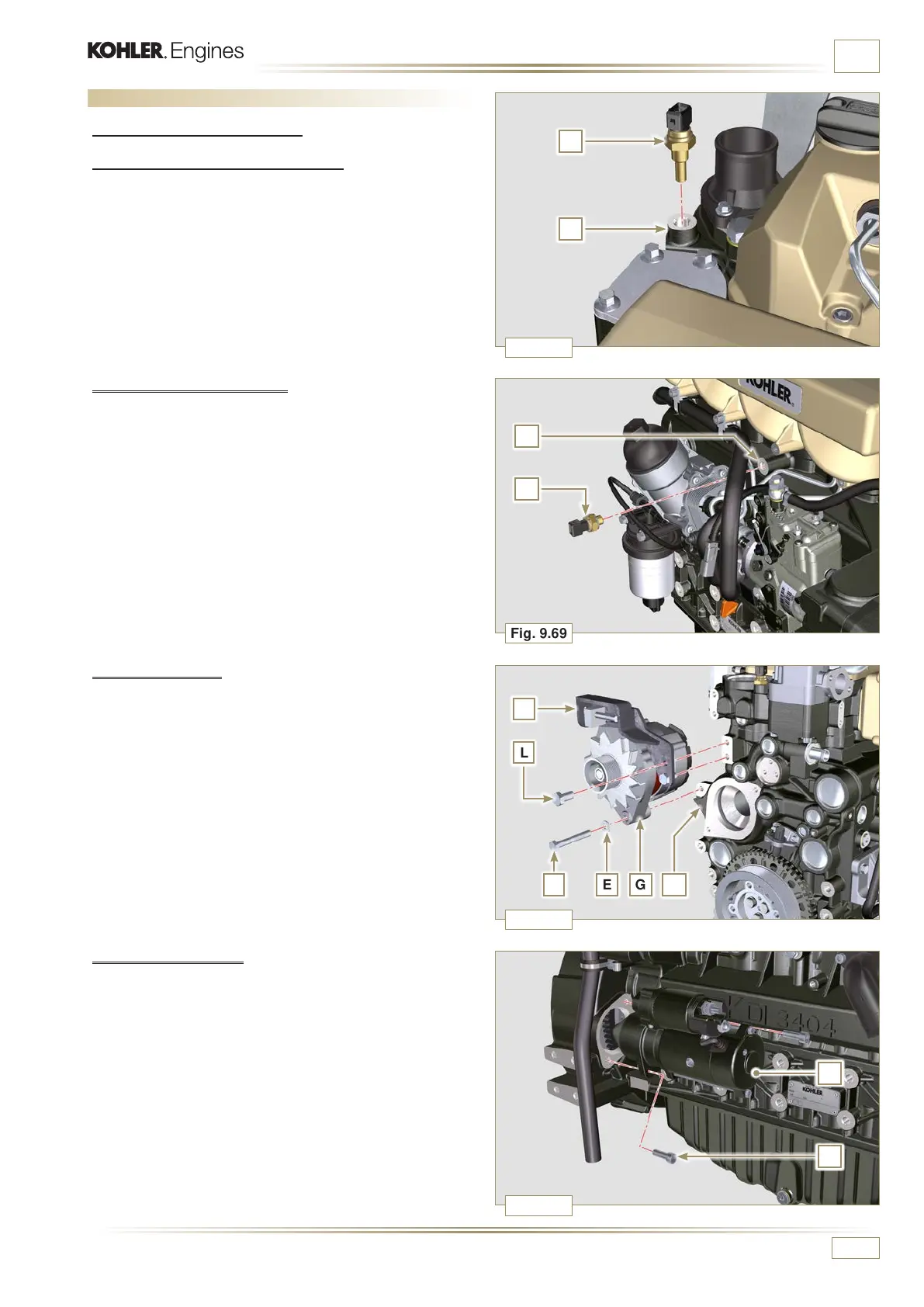
9.13.1 Sensors and switches
9.13.1.2 Coolant temperature sensor
1 - Secure the sensor A onto the head B (tightening torque of
20 Nm).
9.13.1.3 Oil Pressure Switch
1 - Clamp the oil pressure switch C on the crankcase D
(tightening torque at 35 Nm).
9.13.2 Alternator
1 - Insert the washer E onto the screw F.
2 - Insert the screw F onto the alternator G.
3 - Secure the bracket H and the alternator G using the screws
L, F onto the crankcase M.
4 - Follow operations 3, 4, 5, 6 and 7 of Par. 6.2.2.
9.13.3 Starter Motor
1 - Secure motor N by means of capscrews P (tightening torque
at 45 Nm).

 Loading...


