120
G
E
F
H
Fig. 9.64
H
G
E
A
C
M
P
N C B
D
F
Q
S E
P
R
S Q
R
Fig. 9.65
Fig. 9.66
Fig. 9.67
ED0053030410
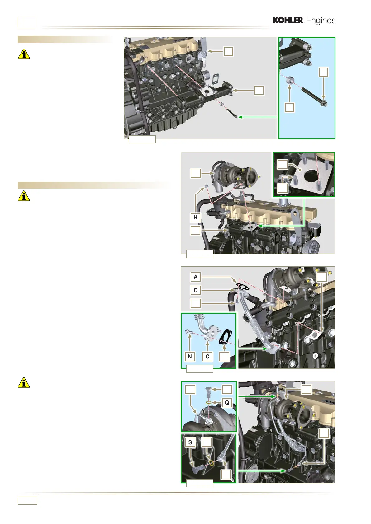
ASSEMBLY INFORMATION
9.11 Exhaust manifold assembly
Important
• Replace the metal gaskets A every
time they are assembled.
1 - Check that the contact surfaces D
are free from impurities.
2 - Position manifold E onto cylinder
head G by manually tightening
capscrews F, inserting:
- gaskets A between cylinder head
G and manifold E;
- spacers H between capscrews F
and manifold E..
3 - Secure manifold E onto cylinder head G by means of
capscrews F (tightening torque 25 Nm).
9.12 Turbocharger Assembly
Important
• Before proceeding, perform the operation described in
Par. 2.18.
• Ensure that tube C is not clogged.
• Always replace the gaskets A, B, Q at each assembly.
• Remove the plastic or foam caps from the turbo compressor
before assembling.
1 - Check that the contact surfaces D are free from impurities
deformations or cracks, otherwise replace damaged
component.
2 - Position the turbo-compressor E on the bolts F on the
manifold G.
3 - Fasten the turbo-compressor E with the nuts H (tightening
torque of 25 Nm).
4 - Fasten the pipe C with the screws M to the turbo-
compressor E.
5 - Fasten the pipe C with the screws N on the crankcase P.
Important
• Always replace the gasket Q after each assembly.
• Before assembly of the tube R, perform the operation
described in Par. 2.18.2 - Point 2.
• Ensure that tube R is not clogged.
6 - Fasten the pipe R with the fittings S on the turbo-compressor
E and on the crankcase P (tightening torque of 15 Nm).
Insert the gaskets Q between:
- S and R;
- E and R;
- P and R.

 Loading...


