132
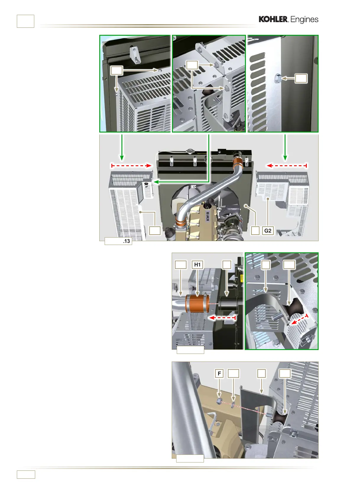
Fig. 11.13
Fig. 11.14
Fig. 11.15
G1 G2
C
E1
E2
E3
H1 C
S
SF
V2
V2F1
J1
ED0053030410
INFORMATION ABOUT OPTIONAL COMPONENTS
4 - Position floodgate G1 onto
radiator C.
5 -
Secure all capscrews E1.
6 -
Place floodgate G2 onto
radiator C.
7 -
Secure all capscrews E3
and E2.
8 - Fit hose H1 onto radiator C, being careful not to deform
tube J1.
NOTE: Make sure vibration-dampening device V2 is correctly
installed in its place on brace S.
9 -
Secure vibration-dampening device V2 onto brace S by
means of nut F, inserting washer F1 (tightening torque at
25 Nm).
10 -
S e cure hoses B and D by means of clamps A2 and A3
(Fig. 11.5 - 11.6).
11 -
S e cure hoses H1 and H2 by means of clamps A1 and A4
(Fig. 11.5 - 11.6).

 Loading...


