28
1
2
3
4
5
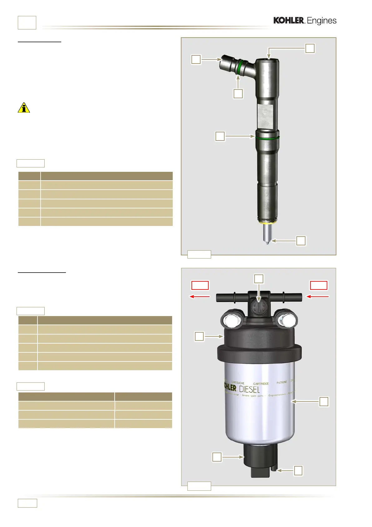
Fig. 2.6
OUT IN
2
3
4
1
5
Tab. 2.14
Tab. 2.15
Tab. 2.16
Fig. 2.7
ED0053030410
TECHNICAL INFORMATION
POS. COMPONENTS DESCRIPTION
1 Inlet fuel
2 Gasket
3 Gasket
4 Nozzle
5 Hole for fuel return to fuel tank
2.9.4 Injector
It is a device used to introduce fuel, in the form of one or more
jets that are adequately pulverised and suitably oriented directly
into the combustion chamber. They consist of a metallic body
that internally provides a mobile element that acts on the
needle: this, rising against the action of a calibrated spring,
allows the release of fuel under high pressure.
Important
• The injectors are calibrated individually.
• Fuel contamination causes serious damage to the injection
system.
2.9.5 Fuel lter
The fuel lter is situated on the crankcase of the engine or it
may be assembled on the frame of the vehicle.
POS. COMPONENTS DESCRIPTION
1 Fuel lter support cartridge
2 Air bleeding screw
3 Cartridge
4 Water draining device
5 Hole water drainage
Cartridge characteristics.
DESCRIPTION VALUE
Filtering surface 2,300 cm
2
Degree of ltration 5 µm
Max operating pressure 2.0 Bar

 Loading...


